Laser machining head and laser machining method thereof

A laser processing head and laser technology, applied in laser welding equipment, metal processing equipment, manufacturing tools, etc., can solve the problems of low processing efficiency, limited processing efficiency, and reduced collimation, so as to improve processing efficiency and improve processing efficiency. High and vertical effect

Inactive Publication Date: 2015-09-30
LASER FUSION RES CENT CHINA ACAD OF ENG PHYSICS
View PDF6 Cites 4 Cited by
  • Summary
  • Abstract
  • Description
  • Claims
  • Application Information

AI Technical Summary

Problems solved by technology

The stability of the external optical path system has a great influence on laser processing, and the processing of workpieces with special structures requires frequent changes in the external optical path system, which limits the processing efficiency to a certain extent
[0004] In addition, for the drilling of the workpiece, the traditional laser processor has a large divergence angle after focusing, and the collimation degree is reduced. Therefore, the wall of the punched hole will have a certain inclination angle. Solve the problem of verticality, but its processing efficiency is low and the stability is not high
[0005] Therefore, traditional laser processors have the disadvantages of low processing efficiency and poor stability for complex components

Method used


Image

  • Laser machining head and laser machining method thereof
  • Laser machining head and laser machining method thereof
  • Laser machining head and laser machining method thereof

Examples


Embodiment 1

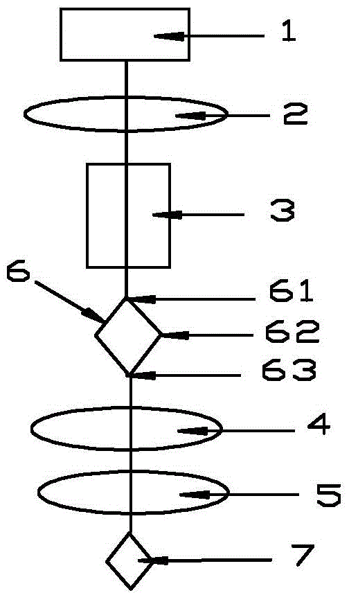
[0028] A laser processing head mainly includes: a laser 1, a focusing lens 2, a biaxial crystal 3 and a zoom system. The zoom system consists of a first convex lens 4 and a second convex lens 5 arranged on a common optical axis, which are arranged in sequence according to the direction of laser transmission: laser 1, focusing lens 2, biaxial crystal 3, first convex lens 4 and second convex lens 5. The focus of the focusing lens 2 is located between the biaxial crystal 3 and the zoom system, the laser output from the laser 1 is parallel to the optical axis of the biaxial crystal 3, and the focusing lens 2 is coated with The film with high transmittance to laser light is coated on the incident surface and exit surface of the biaxial crystal 3, and the film with high transmittance to laser light is coated on the first convex lens 4 and the second convex lens 5. rate film. The biaxial crystal 3 can be rotated to ensure that the converged light beam is parallel to the optical axis...

Embodiment 2

[0052] The same part as embodiment 1 will not be repeated, and the difference is:

[0053] The present invention also provides a method for laser processing using the laser processing head as described above, comprising the following steps:

[0054] (1) After the laser light output by the laser device 1 passes through the focusing lens 2, a converging beam is obtained, and the beam waist radius of the converging beam is ω;

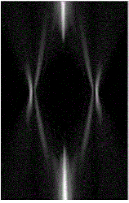
[0055] (2) The converging light beam is incident on the biaxial crystal 3. When it is incident, the converging light beam is parallel to the optical axis of the biaxial crystal 3. After passing through the biaxial crystal 3, a bottle-shaped beam 6 is obtained. The bottle-shaped light beam 6 has a double focus (front Focus 61 and back focus 63), and the focal image plane 63 place is annular;

[0056] (3) Use the focal image plane 62 of the bottle-shaped light beam 6 as the object plane of the zoom system, and use the image plane 7 to punch holes after bein...


PUM


Abstract

The invention discloses a laser machining head and a laser machining method thereof and belongs to the technical field of laser machining equipment and methods. The laser machining head comprises a laser device, a focusing lens and a biaxial crystal which are sequentially arranged as well as a zoom system, wherein the focusing lens and the focus of the focusing lens are located on two sides of the biaxial crystal respectively, the laser output by the laser device is parallel with the optical axis of the biaxial crystal, and the zoom system is arranged on one side of the biaxial crystal, and the focus of the focusing lens is located between the biaxial crystal and the zoom system. The laser machining head is high in machining efficiency and good in stability.

Description

technical field [0001] The invention relates to the technical field of laser processing equipment and methods, in particular to a laser processing head and a laser processing method thereof. Background technique [0002] Due to the continuous development of laser technology and its application, laser processing technology has been paid more and more attention by people. After more than 40 years of development, it has become an important part of advanced manufacturing technology and is currently widely used in automobiles, electronics, electrical appliances, and aviation. , metallurgy, machinery manufacturing and other fields, has huge economic and social benefits, and has a very broad application prospect. Laser processing is non-contact processing, with fast processing speed and no noise, and can achieve high-precision processing purposes of various complex surfaces. And there is no "prop" wear during the processing, and there is no "cutting force" on the workpiece. Speci...

Claims


Application Information

Patent Timeline
IPC IPC(8): B23K26/064B23K26/382
CPCB23K26/0648
Inventor 孙喜博耿远超刘兰琴黄晚晴张颖王文义张森张永亮康民强
Owner LASER FUSION RES CENT CHINA ACAD OF ENG PHYSICS
Why Eureka
Try Eureka