Glove transferring and stacking manipulator system and glove transferring and stacking method

A technology of manipulators and grasping manipulators, which is applied in the direction of conveyor objects, object stacking, transportation and packaging, etc., can solve the problems of unable to meet the production speed and production process requirements, slow glove transfer speed, low production efficiency, etc., to achieve The working speed is fast, the working environment is pollution-free, and the effect of improving work efficiency

Active Publication Date: 2015-09-30
ZIBO CHENGXUN AUTOMATION EQUIP
View PDF7 Cites 21 Cited by
  • Summary
  • Abstract
  • Description
  • Claims
  • Application Information

AI Technical Summary

Problems solved by technology

The glove stacking work at this stage is basically done manually, and the production efficiency is low
There are also some enterprises that have developed a variety of mechanical equipment for glove transfer and st

Method used


Image

  • Glove transferring and stacking manipulator system and glove transferring and stacking method
  • Glove transferring and stacking manipulator system and glove transferring and stacking method

Examples


Embodiment 1

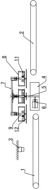
[0027] Embodiment 1, with reference to attached Figure 1-2 : The glove transfer and stacking manipulator system includes a glove feeding belt 1, a glove output belt 2, a visual inspection system 3 and a grabbing manipulator system. A visual inspection system 3 is installed above the glove feeding belt 1, the visual inspection system 3 includes an industrial camera, the direction of the lens of the industrial camera faces the glove feeding belt 1, and the industrial camera is connected to the control system through a data line. A grabbing manipulator system is installed between the glove feeding belt 1 and the glove output belt 2, and the grabbing manipulator system is connected to the control system, and the control system adopts a PLC programmable control system.

[0028] The grasping manipulator system includes a supporting rotating device, and a plurality of grasping devices rotating with the supporting rotating device as the axis are installed on the upper part of the sup...

Embodiment 2

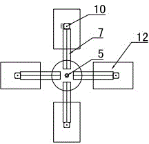
[0037] Embodiment 2, the grasping device is provided with three evenly distributed around the circumference, and the angle between each is 120°. When using the glove transfer and code stack manipulator system to transfer the code stack, in step d, the main motor 6 drives The rotating shaft 5 rotates 120°, and the glove suction cup 12 rotates 120° at the same time to put down the glove for coding. The rest of the settings are the same as in Example 1.

[0038] In the above-mentioned embodiments, according to actual needs, the grasping devices can also be set to two or more other numbers evenly distributed around the circumference.

[0039] The glove transfer and stacking manipulator system can also use electrostatic adsorption to absorb gloves. At this time, there is no need to provide an air suction hole in the glove suction cup 12, and the glove suction cup 12 is equipped with a static electricity generating device that can generate static electricity in the lower part, and ...


PUM


Abstract

The invention provides a glove transferring and stacking manipulator system and a glove transferring and stacking method and belongs to the field of PVC, nitrile and latex glove production equipment. The glove transferring and stacking manipulator system comprises a glove feeding belt (1), a visual detection system (3) and a grabbing manipulator system. The visual detection system (3) is mounted above the glove feeding belt (1). The visual detection system (3) and the grabbing manipulator system are connected with a control system. The grabbing manipulator system comprises a supporting and rotating device. A plurality of grabbing devices rotating with the supporting and rotating device as the axis are mounted at the upper portion of the supporting and rotating device. The grabbing devices are controlled by a plurality of motors to conduct linear movement and angular rotation so as to adapt to the positions and deviation angles, detected by the visual detection system (3), of gloves in the width direction of the glove feeding belt (1). The lower portions of the grabbing devices grab the gloves through a vacuum suction mode or an electrostatic adsorption mode. The glove transferring and stacking manipulator system is simple in structure, high in glove transferring speed, tidy in stacking and capable of improving production efficiency.

Description

technical field [0001] A glove transfer and coding manipulator system and a glove transfer and coding method belong to the field of PVC, nitrile and latex glove production equipment, and specifically relate to an automatically controlled glove transfer and coding equipment and a transfer and coding method. Background technique [0002] In the later stage of the production process of PVC, nitrile and latex gloves, gloves transfer and stacking work are required. The glove stacking work at this stage is basically done manually, and the production efficiency is low. There are also some companies that have developed a variety of mechanical equipment for glove transfer and stacking, but there are shortcomings such as slow glove transfer speed, folding and irregular stacking, and cannot meet the needs of enterprises with high production speed and production technology requirements. Contents of the invention [0003] The technical problem to be solved by the present invention is:...

Claims


Application Information

Patent Timeline
IPC IPC(8): B65G47/91B65G61/00
Inventor 王秀鹤程振中齐建国徐连国
Owner ZIBO CHENGXUN AUTOMATION EQUIP
Why Eureka
Try Eureka