Solid propellant flameout critical pressure reduction rate testing method

A technology of solid propellant and depressurization rate, which is applied in the direction of chemical analysis by means of combustion, can solve the problems of difficult control of initial pressure, uncertain pressure of test samples, initial pressure fluctuations, etc., and achieve the effect of expanding the test range

Inactive Publication Date: 2015-09-30
XIAN MODERN CHEM RES INST
View PDF3 Cites 13 Cited by
  • Summary
  • Abstract
  • Description
  • Claims
  • Application Information

AI Technical Summary

Problems solved by technology

[0006] 1. In the prior art, copper sheets, aluminum sheets and iron sheets with a certain thickness are selected as pressure relief fragments, and the uniformity and consistency of the thickness cannot be guaranteed during the processing; at the same time, the pressure relief fragments that are manually installed in place are squeezed Force and shear also do not guarantee consistency
In other words, the uncertainty of the strength of the pressure relief fragments will make it difficult to control the initial pressure in the combustion chamber within the allowable range, and the initial pressure fluctuations of each experiment are relatively large
[0007] 2. The existing technology cannot guarantee that the test sample will not be ignited during the pressure build-up process of the combustion chamber, nor can it guarantee that the test sample can be ignited after the completion of the p

Method used


Image

  • Solid propellant flameout critical pressure reduction rate testing method
  • Solid propellant flameout critical pressure reduction rate testing method
  • Solid propellant flameout critical pressure reduction rate testing method

Examples


Embodiment Construction

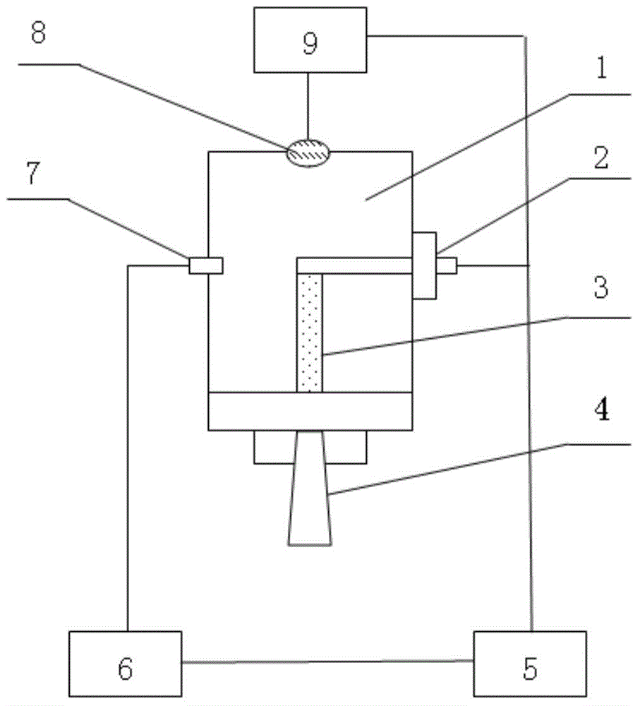
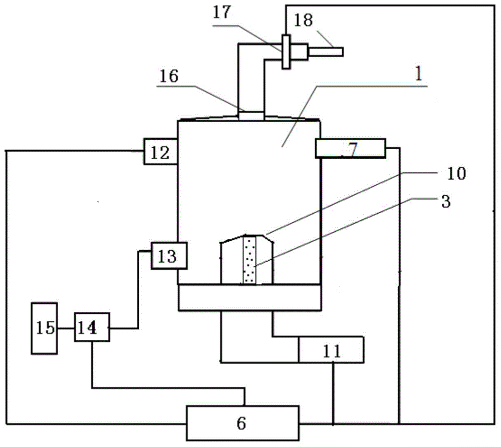
[0032] refer to figure 1 , 2, the main device that the present invention adopts is combustion chamber 1, is made of stainless steel, and volume is about 80ml ± 10ml, should be qualified through resistant 45MPa hydrostatic test. There are holes for testing pressure and testing light intensity on the side wall of combustion chamber 1, and pressure sensor 7 and photoelectric sensor 12 are installed respectively. The pressure sensor 7 adopts a pressure transmitter with a model of CYG41000 and a range of 0-30 MPa; the photoelectric sensor 12 adopts a photomultiplier tube in the infrared band, with a DC output of 0-10V. The lower part of the combustion chamber 1 is provided with an air inlet 13, and the air inlet 13 is connected with a booster pump 14 and a high-pressure gas cylinder 15 with a stainless steel pipe. , cylinder pressure: 13.5±0.5MPa, purity: N 2 ≥99.5%. The top of the combustion chamber 1 is a gas outlet, and a filter screen 16 is installed at the outlet, and is c...


PUM

PropertyMeasurementUnit
The inside diameter ofaaaaaaaaaa

Abstract

The invention discloses a solid propellant flameout critical pressure reduction rate testing method. The method includes the following steps: a high pressure nitrogen gas cylinder serves as a gas source, initial pressure is provided for a testing sample in a burning chamber through a booster pump, the pressure in the burning chamber rises to a threshold value through fuel gas after the sample is lighted, a high pressure electromagnetic valve is opened, and gas discharging is adjusted through the gas discharging amount. A data collection control system records changes of the pressure and the light strength in the burning chamber in the experiment process, the gas discharging amount is adjusted according to the calculated pressure descending rate and the condition whether the sample extinguished or not, and an experiment is performed again. According to the solid propellant flameout critical pressure reduction rate testing method, the problem that the initial pressure in the prior art is large in fluctuation is solved; by means of the method, the minimum flameout pressure reduction rates of different formula propellants under a certain pressure can be tested, the solid propellant flameout critical pressure strength under a certain condition can be tested, the testing range in the prior art is expanded, and the method can be used for testing the solid propellant pressure reduction flameout performance of energy management type tactical missiles and rocket projectiles.

Description

technical field [0001] The invention relates to a method for testing the critical depressurization rate of flameout after combustibles are burned, in particular, it is applied to the test of the critical depressurization rate of flameout of propellants and propellants. Background technique [0002] In order to improve the maneuverability, penetration capability and hit accuracy of the missile, the rocket engine as the power device needs to have the ability to control the thrust and to start multiple times. In order to realize the controllable thrust of the rocket engine and multiple starts, it is necessary to study the flameout engine technology. The key to the flameout engine technology is the study of the flameout conditions of solid propellants, and the critical depressurization rate, that is, the minimum depressurization rate for flameout under a certain pressure is the flameout condition. The key performance parameters studied are also the key design basis for rocket en...

Claims


Application Information

Patent Timeline
IPC IPC(8): G01N31/12
Inventor 王瑛陈雪莉张晓宏赵凤起罗阳张丽涵高红旭肖立柏李娜曲文刚
Owner XIAN MODERN CHEM RES INST
Why Eureka
Try Eureka