
Formation method of semiconductor device

A semiconductor and device technology, applied in the field of semiconductor device formation, can solve the problems of poor etching layer morphology and low production yield of semiconductor devices, etc., achieve good morphology, eliminate bad problems, and improve the effect of morphology

Active Publication Date: 2015-09-30
SEMICON MFG INT (SHANGHAI) CORP
View PDF5 Cites 4 Cited by
  • Summary
  • Abstract
  • Description
  • Claims
  • Application Information

AI Technical Summary

Problems solved by technology

[0004] However, using the method of the prior art, after etching to form the etching layer, the morphology of the etching layer in the pattern sparse area is poor, so that the production yield of the semiconductor device is low

Method used


Image

  • Formation method of semiconductor device
  • Formation method of semiconductor device
  • Formation method of semiconductor device

Examples


Embodiment Construction

[0035] It can be seen from the background technology that when the layer to be etched includes a pattern-dense area and a pattern-sparse area, after the etching is completed, the morphology of the etched layer formed in the pattern-sparse area needs to be improved.

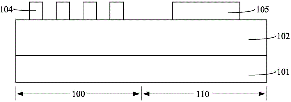
[0036] For research on the formation process of semiconductor devices, please refer to figure 1 , provide a substrate 101, the substrate 101 includes a pattern dense area 100 and a pattern sparse area 110; form a layer 102 to be etched on the surface of the substrate 101; form an initial photoresist layer on the surface of the layer to be etched Exposing and developing the initial photoresist layer, forming a first photoresist layer 104 with a dense pattern on the surface of the layer to be etched in the pattern-intensive area 100, and forming a first photoresist layer 104 with a dense pattern in the pattern-intensive area 110 to be etched. A second photoresist layer 105 with sparse patterns is formed on the surfac...


PUM


Abstract

A formation method of a semiconductor device includes providing a substrate having a to-be-etched layer including a graph dense zone and a graph sparse zone; forming a first mask layer having sparse images on the surface of the graph sparse zone of the to-be-etched layer; forming a photo-etching layer covering the surface of the to-be-etched layer and the surface of the first mask layer; performing exposure development on the photo-etching layer and forming a second mask layer having dense images on the image dense zone of the to-be-etched layer and the surface of the first mask layer; etching the graph dense zone of to-be-etched layer by taking the second mask layer as a mask and etching the graph sparse zone of the to-be-etched layer by taking the second mask layer and the first mask layer as the mask until the surface of the substrate is exposed. By adopting the invention, problems caused by load effect during an etching process can be solved, so that the etching layer formed after the etching process of the graph sparse zone has a good appearance.

Description

technical field [0001] The invention relates to the field of semiconductor manufacturing, in particular to a method for forming a semiconductor device. Background technique [0002] In the integrated circuit manufacturing process, the photoresist (PR: Photo Resist) covering the surface of the semiconductor substrate is exposed and developed to form a patterned photoresist layer, and then the pattern in the photoresist layer is etched by etching technology. transferred to a semiconductor substrate to form an integrated circuit structure. [0003] Generally, the pattern density of each region of the semiconductor substrate is different, and the semiconductor substrate includes a pattern dense area (Dense Area) and a pattern sparse area (ISO Area). The process steps of forming semiconductor substrates with different pattern densities include: forming a patterned photoresist layer on the surface of the semiconductor substrate. Relatively speaking, the pattern density of the pho...

Claims


Application Information

Patent Timeline
Patent Type & Authority Applications(China)
IPC IPC(8): H01L21/70
CPCH01L21/0271H01L21/70
Inventor 王新鹏
Owner SEMICON MFG INT (SHANGHAI) CORP
Learn More