Micro vibration sensor

A sensor and micro-vibration technology, which is applied in the field of sensors, can solve the problems of limited sensitivity, high signal-to-noise ratio of output signal, and inability to convert mechanical energy into electrical energy, so as to achieve the effect of improving sensitivity and signal-to-noise ratio

Active Publication Date: 2017-01-18
NEWNAGY TANGSHAN
View PDF6 Cites 0 Cited by
  • Summary
  • Abstract
  • Description
  • Claims
  • Application Information

AI Technical Summary

Problems solved by technology

However, due to the relatively consistent area size of each layer, it is not conducive to the transmission of vibration and pressure when used as a micro-vibration sensor, so its sensing sensitivity is low. When the vibration or pressure is small, for example, liquid dripping, respiratory airflow Under such weak stress conditions, it cannot convert mechanical energy into electrical energy and output electrical signals
Therefore, it cannot be applied to breathing intensity detection or other micro-vibration sensors with high sensitivity requirements, such as micro-acceleration sensors, and micro-medical devices implanted in human blood vessels and organs, etc.
[0004] In addition, micro-vibration sensors used in precision applications such as electronic devices are susceptible to external electromagnetic interference, resulting in an excessively high signal-to-noise ratio of the output signal, and usually require electromagnetic shielding, which increases the cost and is not conducive to the miniaturization of the device. also further limits the sensitivity

Method used


Image

  • Micro vibration sensor
  • Micro vibration sensor
  • Micro vibration sensor

Examples


Embodiment Construction

[0029] In order to fully understand the purpose, features and effects of the present invention, the present invention will be described in detail through the following specific embodiments, but the present invention is not limited thereto.

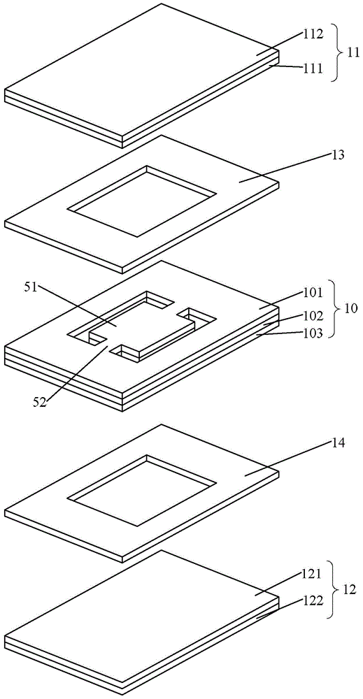
[0030] figure 1 A schematic structural view of a micro-vibration sensor provided by an embodiment of the present invention is shown, as figure 1 As shown, the micro-vibration sensor includes: a first friction layer 11 , a first isolation layer 13 , an intermediate friction layer 10 , a second isolation layer 14 and a second friction layer 12 which are sequentially stacked.

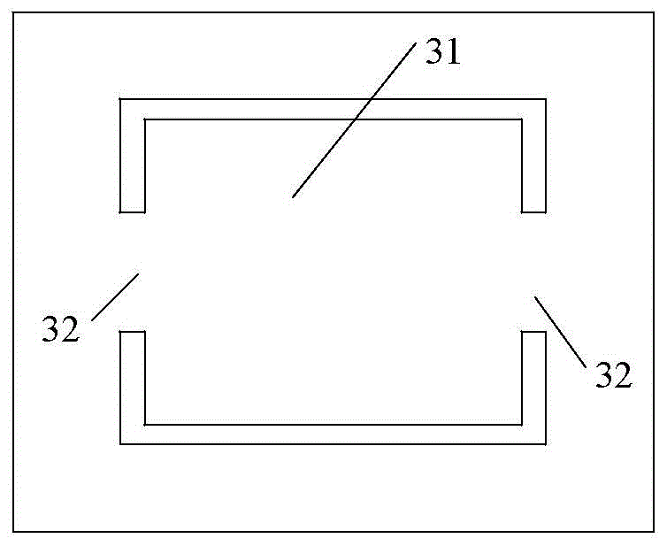
[0031] Wherein, the first friction layer 11 includes a stacked first polymer insulating layer 111 and a first ground electrode 112; similarly, the second friction layer 12 includes a stacked second polymer insulating layer 121 and a second ground electrode. electrode 122 . The middle friction layer 10 has a cantilever beam structure, and the cantilever beam structure...


PUM


Abstract

The invention discloses a micro-vibration sensor, comprising: a first friction layer, a first isolation layer, an intermediate friction layer, a second isolation layer and a second friction layer which are sequentially stacked; The high molecular polymer insulation layer and the ground electrode; the middle friction layer includes the first output electrode and the second output electrode, and is made with a cantilever beam structure; the two sides of the main part pass through the cavity of the first isolation layer and the second The cavity of the isolation layer forms a friction interface with the high molecular polymer insulation layers of the first and second friction layers; the part of the middle friction layer other than the cantilever beam structure passes through the first isolation layer and the second isolation layer and the first friction layer respectively. The high molecular polymer insulating layer and the high molecular polymer insulating layer of the second friction layer are bonded. The cantilever beam structure enables the micro-vibration sensor to sense a small external force, which significantly improves the sensitivity of the sensor, and the ground electrode also plays the role of electromagnetic shielding.

Description

technical field [0001] The invention relates to the field of sensors, in particular to a micro-vibration sensor. Background technique [0002] Micro-vibration sensors are widely used in various fields such as electronics, machinery, and biology. They usually use the tiny deformation of tiny mechanical components to output electrical signals of different sizes, and obtain corresponding information by analyzing the changes in electrical signals. Generally, the micro-vibration sensor is powered by an external power source, electromagnetic, piezoelectric, etc., but this requires an independent power supply device, which makes the structure very complicated. [0003] Due to its self-powered advantage, the friction generator does not require external power supply, and friction generators of different structures and materials are successively used in micro-vibration sensors. The triboelectric generator is generally composed of sequentially stacked electrode layers and polymer insu...

Claims


Application Information

Patent Timeline
Patent Type & Authority Patents(China)
IPC IPC(8): H02N1/04G01H11/06
Inventor 叶柏盈王雪崔婧
Owner NEWNAGY TANGSHAN
Why Eureka
Try Eureka