A sensorless predictive torque control system and method for an asynchronous motor

A technology for asynchronous motors and torque prediction, applied in control systems, vector control systems, motor generator control, etc., can solve problems such as insufficient control accuracy

Inactive Publication Date: 2017-10-24
QUANZHOU INST OF EQUIP MFG
View PDF5 Cites 0 Cited by
  • Summary
  • Abstract
  • Description
  • Claims
  • Application Information

AI Technical Summary

Problems solved by technology

[0005] The invention provides a sensorless predictive torque control system and method for asynchronous motors, which overcomes the shortcomings of insufficient control accuracy in the existing sensorless control of asynchronous motors. And calculate the cost value g of the evaluation function j , get g j The reference voltage vector vs* at the minimum value, and convert it to the corresponding switch value S a,b,c Used as a control signal to control the inverter to output the optimal voltage value to the asynchronous motor to achieve high-precision control of the asynchronous motor

Method used


Image

  • A sensorless predictive torque control system and method for an asynchronous motor
  • A sensorless predictive torque control system and method for an asynchronous motor
  • A sensorless predictive torque control system and method for an asynchronous motor

Examples


Embodiment 1

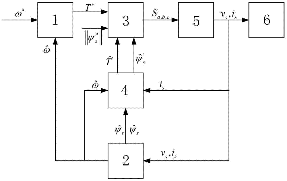
[0098] like Figure 1-2 As shown, a sensorless predictive torque control system for an asynchronous motor according to the present invention includes a first PI controller 1, a model reference adaptive observer 2, and an optimization module 3; the first PI controller 1, and an optimization module 3 The model reference adaptive observer 2 is connected to each other in pairs; the asynchronous motor sensorless predictive torque control system is connected to the inverter 5 when used, and the inverter 5 is connected to the asynchronous motor 6;

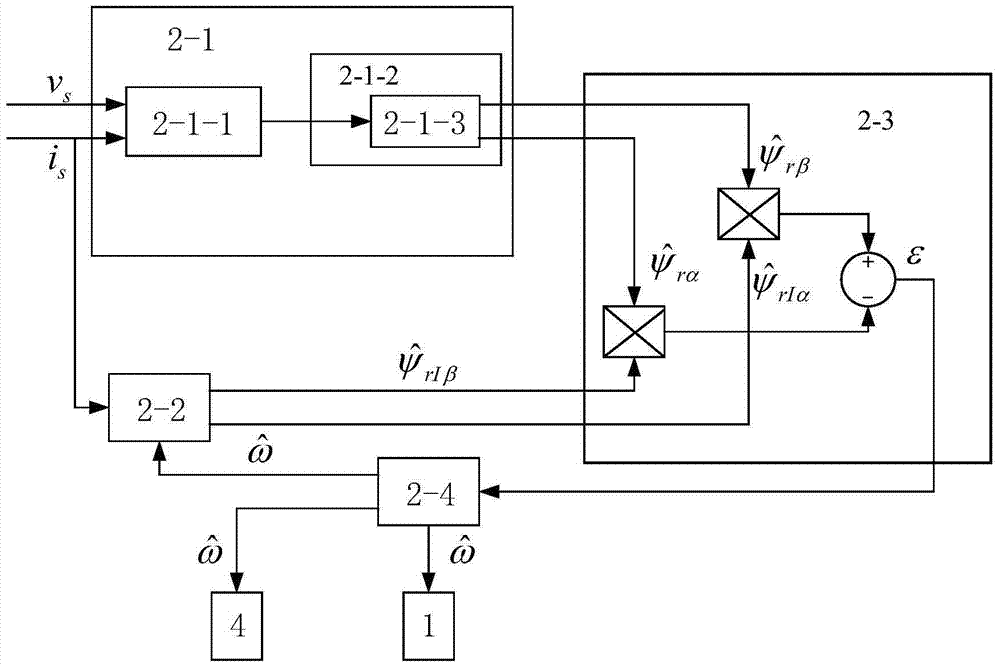
[0099] The model refers to an adaptive observer 2 for the stator voltage v obtained at the output of the inverter 5 s and stator current i s Calculate the observed speed by formula 1-4 The model reference adaptive observer 2 includes a reference module 2-1, an adjustable module 2-2, a rotor flux deviation calculation module 2-3 and a second PI controller 2-4, a reference module 2-1, an adjustable module 2-2 are respectively connected ...

Embodiment 2

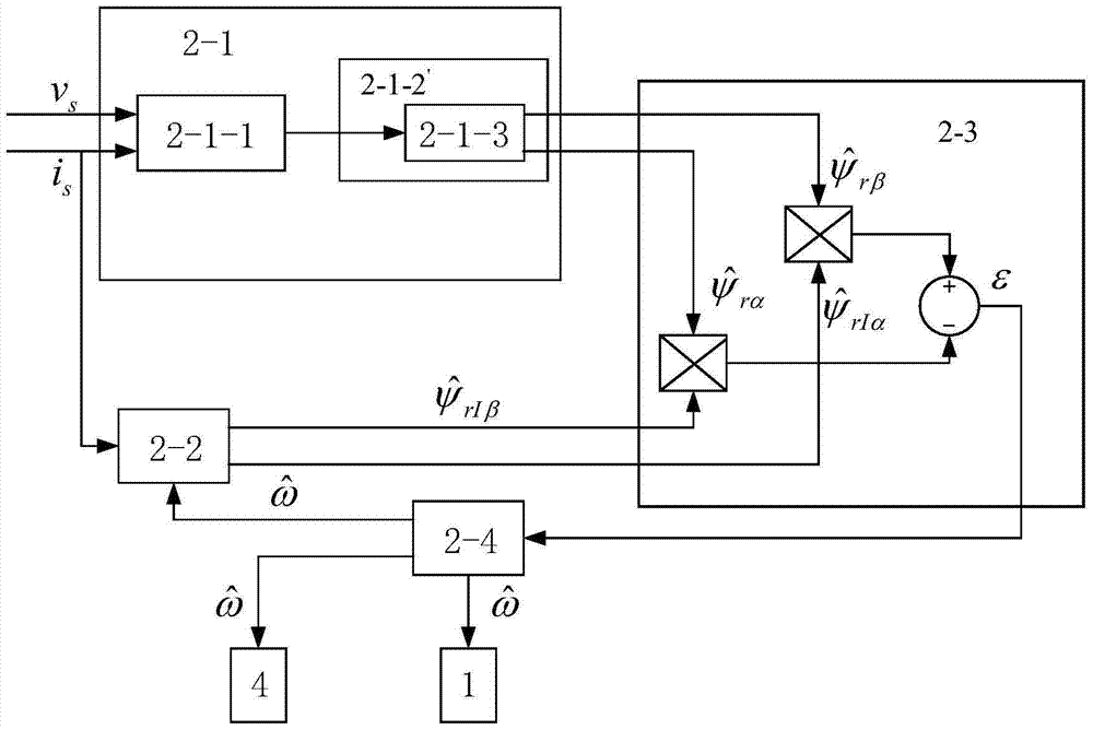
[0133] like figure 1 , 3 As shown, it differs from Embodiment 1 in that:

[0134] The sliding mode compensation module 2-1-2 is replaced by the sliding mode compensation optimization module 2-1-2', and the third PI controller 2-1-3 in the sliding mode compensation optimization module 2-1-2' utilizes Self-adjustable proportional gain of K kp and integral gain K ki The sliding mode gain K is calculated by formula 5, and the sliding mode gain K is used for sliding mode compensation, and formula 1 is corrected to formula 1", the above formula is as follows,

[0135]

[0136]

[0137]

[0138] Among them, Sat(S) is a continuous function with saturation characteristics, x=i sα and i sβ , Δ is a non-negative adjustment parameter.

[0139] In order to further verify the effectiveness of the observer proposed in this implementation example and the overall performance of the sensorless control system based on the observer, this embodiment is applied to an asynchronous m...


PUM


Abstract

The invention relates to a sensorless predictive torque control system for an asynchronous motor, comprising a first PI controller, a model reference adaptive observer, and an optimization module; two pairs of the first PI controller, the optimization module, and a model reference adaptive observer interconnected; the sensorless predictive torque control system of the asynchronous motor is connected to the inverter through the optimization module, and the inverter is connected to the asynchronous motor. The reference module also includes a sliding mode compensation module, and a torque and flux linkage prediction module is installed between the model reference adaptive observer and the optimization module. This invention applies to overcome the lack of control accuracy existing in the existing sensorless control of asynchronous motors. By obtaining the observed speed and calculating the cost value gj of the evaluation function, the reference voltage vector vs* at the minimum value of gj is obtained, and converted into corresponding switching values ​​Sa, b, c as control signals to control the inverter Output the optimal voltage value to the asynchronous motor to achieve high-precision control of the asynchronous motor.

Description

technical field [0001] The invention relates to a sensorless predictive torque control system and method for an asynchronous motor. Background technique [0002] The vector control of an asynchronous motor requires information on the rotational speed of the motor. The traditional AC asynchronous motor control system mostly uses magnetic field positioning control and direct torque control technology, which requires the installation of a speed sensor, which is costly, and the measurement of the rotational speed through the signal obtained by the encoder will be difficult. Problems such as errors caused by installation, measurement and transmission disturbances arise. The predictive torque control technology that has not been widely used has the advantages of intuitive and easy-to-understand algorithms, and can handle complex control tasks and multi-variable and multi-constraint control problems. It can achieve accurate and efficient motors by identifying and predicting some mo...

Claims


Application Information

Patent Timeline
Patent Type & Authority Patents(China)
IPC IPC(8): H02P21/00H02P21/20
Inventor 汪凤翔梅雪竹柯栋梁
Owner QUANZHOU INST OF EQUIP MFG
Why Eureka
Try Eureka