Jitter tolerance testing method and circuit for high-speed serial IO interface based on BIST

A jitter tolerance test, high-speed serial technology, applied in the direction of line transmission monitoring/testing, line transmission components, etc., can solve the problems of not being able to simulate the actual situation well, complex jitter components, complex circuit implementation, etc., to achieve Reduce testing costs, reduce dependencies, and achieve simple effects

Inactive Publication Date: 2015-09-30
PEKING UNIV
View PDF4 Cites 19 Cited by
  • Summary
  • Abstract
  • Description
  • Claims
  • Application Information

AI Technical Summary

Problems solved by technology

The two major problems faced by the jitter tolerance test are: ① Most of the bus standards require a BER≤10 -12 Under the jitter tolerance test, the device must send at least 10 13 A bit of data, and the jitter tolerance test needs to test multiple frequencies, which will make the test time very long; ②The jitter tolerance test needs to generate different types of jitter and mix them to produce controllable jitter close to the real ratio The composition is more complicated
These methods can inject SJ very well and perform jitter tolerance test on the circuit under test, but these methods can only inject PJ of a single frequency, which cannot simulate the actual situation well
Ahmed and Kwasniewski implemented multiple jitter injections through Digital Integrator, Adder, Delay Control Logic and Variable Vernier Delay, but the circuit implementation is complicated and not intuitive enough

Method used


Image

  • Jitter tolerance testing method and circuit for high-speed serial IO interface based on BIST
  • Jitter tolerance testing method and circuit for high-speed serial IO interface based on BIST
  • Jitter tolerance testing method and circuit for high-speed serial IO interface based on BIST

Examples


Embodiment Construction

[0029] In order to make the method and advantages of the present invention more understandable, the BIST-based high-speed serial IO interface jitter tolerance test design scheme provided by the present invention is described in detail below in conjunction with the accompanying drawings, but this does not constitute a limitation of the present invention.

[0030] The present invention is based on the high-speed serial IO interface jitter tolerance test method of BIST, and its implementation steps comprise:

[0031] Phase 1: Build the BIST circuit

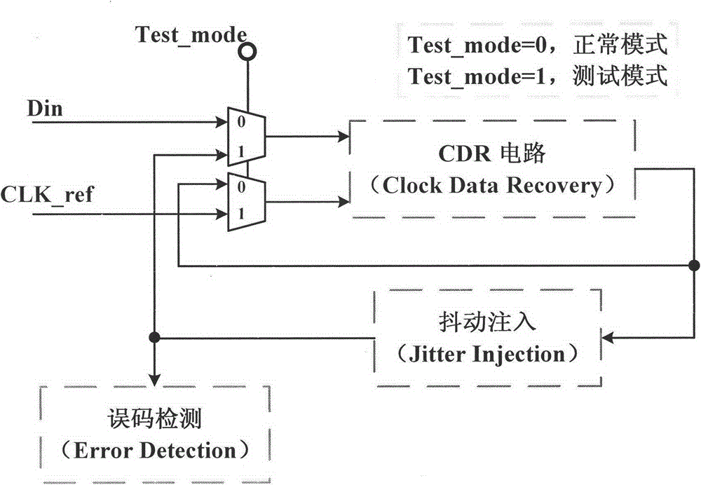
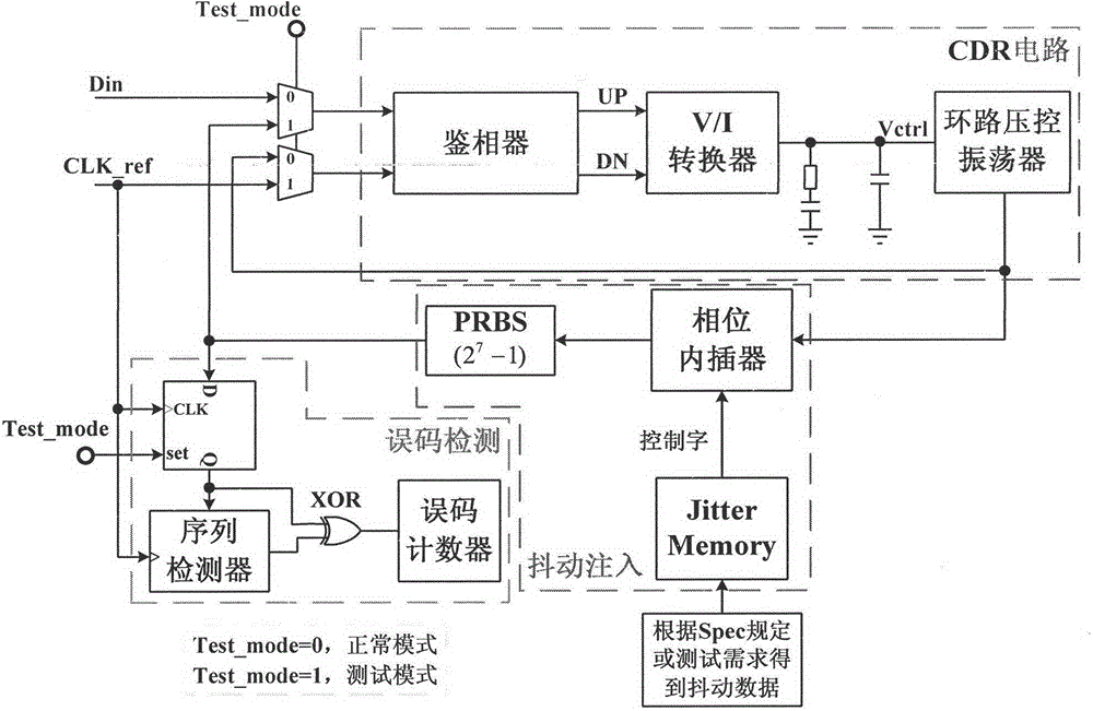
[0032] Step1: After the design of the high-speed serial IO interface circuit is completed, insert the BIST circuit for the jitter tolerance test. Such as figure 1 As shown, the BIST of the present invention includes two parts: jitter injection and bit error detection. Such as figure 2 As shown, the jitter injection module is used to generate a binary sequence containing the jitter information required for testing, including Jitte...


PUM


Abstract

The invention discloses a jitter tolerance testing method and circuit for a high-speed serial IO interface based on BIST (built-in self-test). The circuit mainly consists of a CDR circuit module, a jitter injection module, and an error code detection module. A CDR circuit at the receiving end of the high-speed serial IO interface is additionally provided with the jitter injection module and the error code detection module, and can achieve the self-testing of the jitter tolerance of the receiving end. The jitter injection module comprises a Jitter Memory, a PI (phase interpolator) and a PRBS (pseudorandom binary sequence) circuit, and is used for generating a test sequence containing jitter information. The error code detection module comprises a sequence detector (PRBS Checker), an XOR gate and an error code counter (Error Detection), and is used for detecting an error code and obtaining the number of error codes. The method and circuit achieve the self-testing of the jitter tolerance of the receiving end, and can achieve the different types of jitter injection, such as RJ (random jitter), PJ (periodic jitter), and DCD (duty cycle distortion). The BIST circuit is simple in implementation, effectively shortens the testing time, reduces the testing cost, can be used for various types of high-speed serial IO interface circuits, and is higher in practicality.

Description

technical field [0001] The invention discloses a high-speed serial IO interface jitter tolerance test method and circuit, specifically implementing jitter injection and error code detection inside a receiver circuit of the high-speed serial interface to complete the receiver jitter tolerance test. Background technique [0002] Input / output (I / O) has always played a key role in computer and industrial applications. In the early parallel I / O bus, the data alignment problem of the interface affects the effective communication with external devices. However, with the increase of processor speed, I / O has become the bottleneck of system-level performance, and improving I / O performance is very critical to improve system performance. In the current high-speed communication system, the serial communication technology SerDes (serializer / deserializer) originally used for optical fiber communication has become the key to the high-speed communication system due to its ability to comply ...

Claims


Application Information

Patent Timeline
Patent Type & Authority Applications(China)
IPC IPC(8): H04B3/46
Inventor 冯建华宋京京叶红飞闫鹏张兴
Owner PEKING UNIV
Why Eureka
Try Eureka