Method for manufacturing thermoelectric converter

A technology of thermoelectric conversion and manufacturing method, which is used in the manufacture/processing of thermoelectric devices, thermoelectric device components, thermoelectric devices using only Peltier or Seebeck effects, etc.

Active Publication Date: 2015-09-30
DENSO CORP +1
View PDF8 Cites 6 Cited by
  • Summary
  • Abstract
  • Description
  • Claims
  • Application Information

AI Technical Summary

Problems solved by technology

Therefore, for example, in the case of manufacturing a thermoelectric conversion device in which the through holes are filled only with conductive paste composed of Bi, Te, Se, etc., and the surface pattern and the back pattern are formed of a material different from the alloy in which the conductive paste is solid-phase sintered The above problem also arises under

Method used


Image

  • Method for manufacturing thermoelectric converter
  • Method for manufacturing thermoelectric converter
  • Method for manufacturing thermoelectric converter

Examples


no. 1 approach

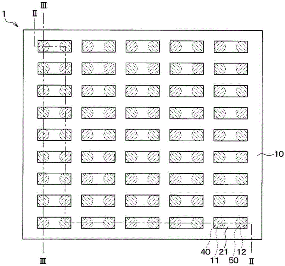
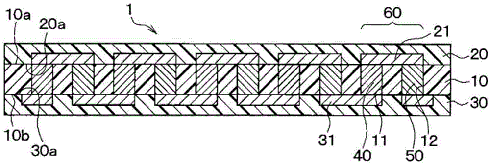
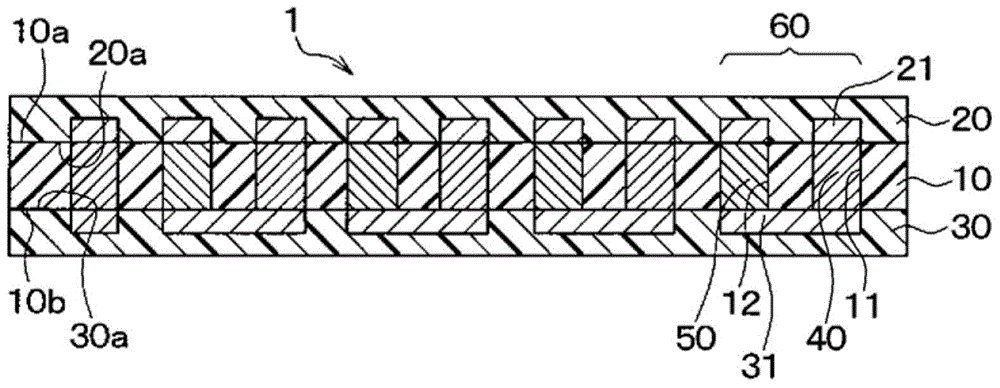
[0038] A first embodiment of the present invention will be described with reference to the drawings. Such as Figure 1 ~ Figure 3 As shown, the thermoelectric conversion device 1 of the present embodiment is constituted by integrating the insulating base material 10, the surface protection member 20, and the back surface protection member 30, and the first interlayer connecting member, which is a first interlayer connecting member, is a dissimilar metal inside the integrated member. 40. The second interlayer connection components 50 are alternately connected in series.

[0039] also, figure 1 For easy understanding, the surface protection member 20 is omitted and shown. in addition, figure 1 Although not a cross-sectional view, hatching is given to the first interlayer connection member 40 and the second interlayer connection member 50 .

[0040] In this embodiment, the insulating base material 10 is composed of a planar rectangular thermoplastic resin film made of polyeth...

no. 2 approach

[0080] A second embodiment of the present invention will be described. In this embodiment, compared with the first embodiment, the plated film is formed after the first interlayer connecting member 40 and the second interlayer connecting member 50 are formed. Since the rest is the same as the first embodiment, description is omitted here.

[0081] Such as Figure 8 As shown, in this embodiment, the Figure 4 After the step (e), a plated film 90 made of Ni or the like is formed on the portions of the first interlayer connecting member 40 and the second interlayer connecting member 50 exposed from the insulating base material 10 .

[0082] In addition, the parts of the first interlayer connecting member 40 and the second interlayer connecting member 50 exposed from the insulating base material 10 are, in other words, regions that are in pressure contact with the surface pattern 21 or the rear surface pattern 31 in the first embodiment. In addition, the plated film 90 is formed...

no. 3 approach

[0085] A third embodiment of the present invention will be described. In the present embodiment, the step of forming the through-hole in the insulating base material 10 is performed as compared with the first embodiment, and since the rest is the same as that of the first embodiment, description thereof will be omitted here.

[0086] Such as Figure 9 as well as Figure 10 As shown, in this embodiment, the Figure 4 After the step (d), the through-hole 13 corresponding to the void of the present invention is formed in the insulating base material 10 by a drill, a laser, or the like. In this embodiment, if Figure 9 as well as Figure 10 As shown, a plurality of cylindrical through-holes 13 separated at equal intervals are formed concentrically, that is, along the circumferential direction, with each of the first through-hole 11 and the second through-hole 12 as the center.

[0087] In addition, the case where the through-hole 13 is cylindrical is described here, but the t...


PUM


Abstract

An insulating substrate (10) in which a plurality of via holes (11, 12) that penetrate said substrate in the thickness direction thereof are filled with a conductive paste (41, 51) is prepared. Said conductive paste (41, 51) is obtained by adding an organic solvent to an alloy powder in which a plurality of metal atoms maintain a prescribed crystal structure. Then, while the insulating substrate (10) is being heated, pressure is applied from the top surface (10a) and the bottom surface (10b) thereof. The conductive paste (41, 51) is thus subjected to solid-state sintering, forming interlayer connection members (40, 50). Next, a top-surface protection member (20) is placed on the top surface (10a) of the insulating substrate (10) and a bottom-surface protection member (30) is placed on the bottom surface (10b) of the insulating substrate (10), forming a laminate (80). Said laminate (80) is then fused into a single unit by the application of simultaneous heat and pressure, albeit at a lower temperature and with less pressure than were used in the step that formed the interlayer connection members (40, 50).

Description

technical field [0001] The present invention relates to a method of manufacturing a thermoelectric conversion device including a step of solid-phase sintering a conductive paste to form an interlayer connection member. Background technique [0002] Conventionally, as a manufacturing method of a thermoelectric conversion device, for example, Patent Document 1 proposes the following manufacturing method. That is, in this manufacturing method, first, through holes are formed in the insulating mold, and the first conductive paste composed of Bi, Te, Se, etc. and the second conductive paste composed of Bi, Sb, Te, etc. are filled regularly. in the through hole. [0003] Furthermore, a plurality of surface patterns in contact with the adjacent first and second conductive pastes are formed on the surface of the insulating template. In addition, on the back surface of the insulating template, a plurality of back patterns in contact with the first conductive paste and a second cond...

Claims


Application Information

Patent Timeline
Patent Type & Authority Applications(China)
IPC IPC(8): H01L35/34
CPCH01L35/34H01L35/32H10N10/817H10N10/01H10N10/17
Inventor 宫川荣二郎斋藤启太白石芳彦矢崎芳太郎谷口敏尚坂井田敦资
Owner DENSO CORP
Why Eureka
Try Eureka