
Precise hole forming drilling machine

A hole drilling machine, precision technology, applied in the direction of boring/drilling, drilling/drilling equipment, parts of boring machine/drilling machine, etc., can solve the problem of deformation measurement of chuck, tool and drill shaft, and the processing accuracy of drill bit can not be obtained Guarantee, parts processing errors and other issues, to achieve the effect of precision improvement, convenient positioning, and precise positioning

Inactive Publication Date: 2015-10-07
刘海明
View PDF4 Cites 10 Cited by
  • Summary
  • Abstract
  • Description
  • Claims
  • Application Information

AI Technical Summary

Problems solved by technology

[0003] In most of the existing drilling machines, it is not possible to measure the deformation of the chuck, tool and drill shaft of the drilling machine, so that the operator can always know the deformation of these parts, so as to ensure that the drilling is safe within the deformation range it can withstand to run
In addition, when processing parts, the positioning of the drill bit is often inaccurate. Once the positioning is not accurate during processing, it will cause processing errors in the processing of the parts, resulting in a high scrap rate of the parts. At present, many drill bits are in use. When the connection with the drilling machine is unstable, the machining accuracy of the drill bit cannot be guaranteed during processing, which makes the vibration of the drill bit larger, which affects the processing quality and has certain safety hazards.

Method used


Image

  • Precise hole forming drilling machine
  • Precise hole forming drilling machine
  • Precise hole forming drilling machine

Examples


Embodiment Construction

[0017] The technical solutions in the embodiments of the present invention will be clearly and completely described below with reference to the accompanying drawings in the embodiments of the present invention. Obviously, the described embodiments are only a part of the embodiments of the present invention, but not all of the embodiments. Based on the embodiments of the present invention, all other embodiments obtained by those of ordinary skill in the art without creative efforts shall fall within the protection scope of the present invention.

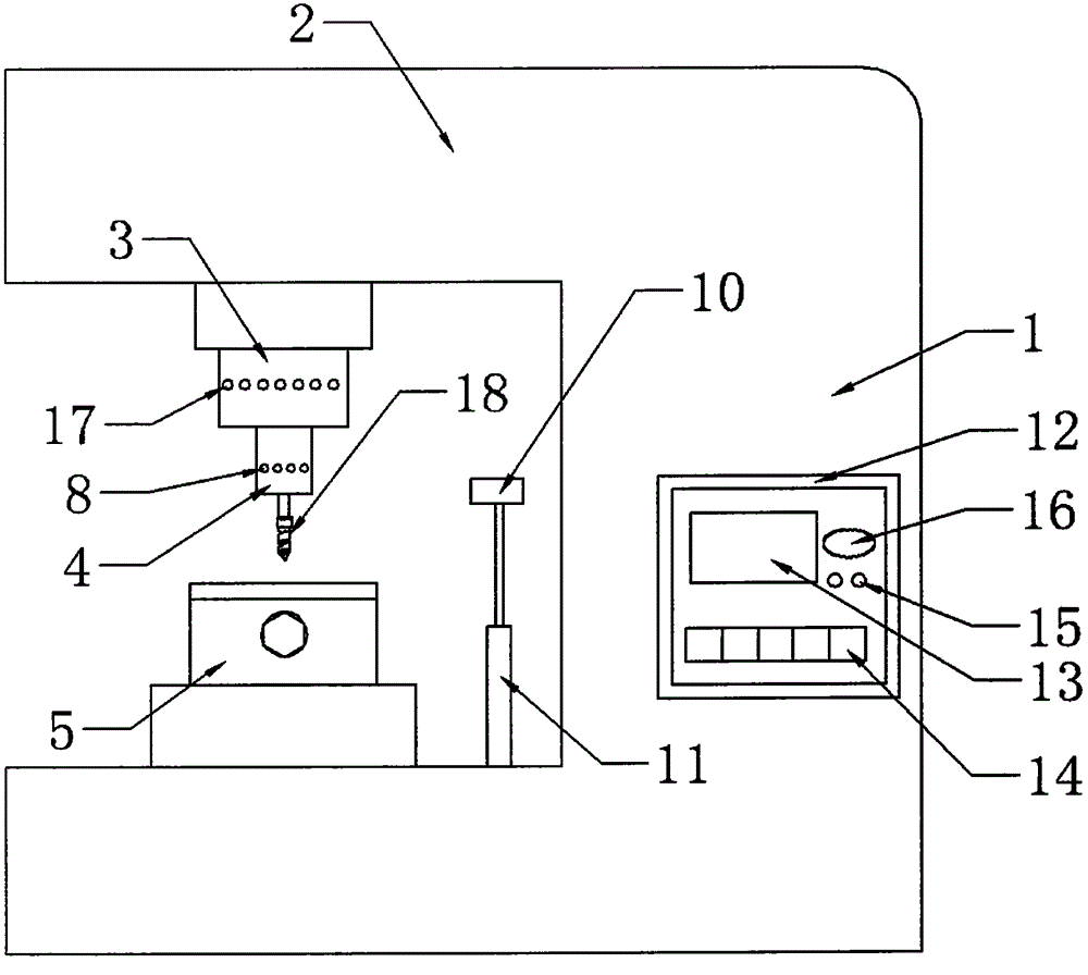
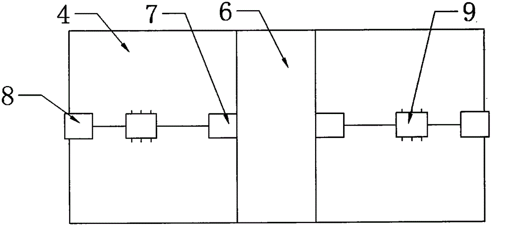
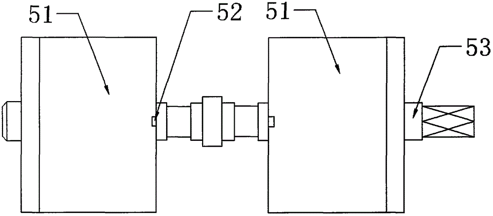
[0018] see Figures 1 to 4 , in an embodiment of the present invention, a precision hole drilling machine includes a body 1, the upper part of the body 1 is a spindle box 2, the bottom of the spindle box 2 is connected to a spindle 3, and the rotation of the spindle 3 drives the chuck 4 located below it, Drill bit 18 is installed in chuck 4 inside, and drill bit 18 comprises head 181 and drill shank 182, and head 181 and drill shank 1...


PUM

PropertyMeasurementUnit
Thicknessaaaaaaaaaa

Abstract

The invention discloses a precise hole forming drilling machine. The precise hole forming drilling machine comprises a machine body. A main shaft box is arranged at the upper portion of the machine body. The bottom of the main shaft box is connected with a main shaft. The main shaft rotates and drives a chuck located below the main shaft. A drill bit is arranged inside the chuck and comprises a head part and a drill handle which are connected with each other. A connecting piece is arranged between the head part and the drill handle. The connecting piece is a circular concave table. Clamping teeth are arranged in the circular concave table and distributed in the circular concave table. The width of the circular concave table ranges from 10 cm to 30 cm. The drill handle is in a cylindrical shape, an anti-skid component is arranged on the drill handle, and the anti-skid component is a corrugated groove. The drill bit is arranged, the connecting piece is arranged to be the circular concave table, and connection between the drill bit and the chuck can be convenient; the clamping teeth are arranged in the circular concave table, the connection between the drill bit and the chuck can be firmer, and the phenomenon of sliding down of the chuck cannot happen. The corrugated anti-skid component is arranged on the drill handle, and the drill bit can be prevented from sliding down in the grabbing process.

Description

technical field [0001] The invention relates to the field of drilling machine technical equipment, in particular to a precision drilling machine. Background technique [0002] Drilling machine refers to a machine tool that mainly uses a drill bit to process holes in a workpiece. Generally, the rotation of the drill bit is the main movement, and the axial movement of the drill bit is the feed movement. The drilling mechanism is simple, and the processing progress is relatively low. Through holes and blind holes can be drilled, special tools can be replaced, and processing such as expansion, countersinking, reaming or tapping can be performed. During the machining process, the workpiece does not move, let the tool move, align the center of the tool with the center of the hole, and rotate the tool. Operation can be manual or motorized. [0003] In most of the existing drilling machines, it is not possible to measure the deformation of the chuck, tool and drill shaft of the d...

Claims


Application Information

Patent Timeline
IPC IPC(8): B23B39/00B23B51/00B23B51/12B23Q15/12B23Q17/00B23Q17/24B23Q3/06
CPCB23B39/00B23B51/00B23B51/12B23B2251/04B23Q3/06B23Q15/12B23Q17/005B23Q17/24
Inventor 刘海明
Owner 刘海明
Learn More