a turbine

A technology of turbines and axles, which is applied in the direction of gas turbine devices, mechanical equipment, machines/engines, etc., can solve the problems of low energy conversion efficiency, impact on blade service life, large pressure loss and energy loss, etc., to achieve efficient use of fuel energy, The effect of improving efficiency and prolonging service life

Active Publication Date: 2016-06-29
邓小波
View PDF9 Cites 3 Cited by
  • Summary
  • Abstract
  • Description
  • Claims
  • Application Information

AI Technical Summary

Problems solved by technology

[0004] As we all know, most of the traditional internal combustion engines are piston-type, and the piston is pushed to do work by igniting the mixture of compressed air and fuel. Because of the discontinuity of its work (four strokes do work once), there is a problem that vibration will be generated, and the self-ignition suction The type of engine is destined to burn insufficiently. If the compressed air is used to make it fully burnt, it will produce a high temperature, which will put forward higher requirements for the cylinder block, piston and lubrication system, and their requirements for fuel are also relatively simple. The machine can only use the fuel it is suitable for
[0009] 1. The gas in the cylinder head is detonated to push the impeller to do work (transmitting kinetic energy outward), and the cylinder is located outside the annular airtight area, so the high-temperature gas due to explosion will not only work on the impeller, but also be absorbed by the cylinder itself Part of the energy, and then there is a problem of large pressure loss and energy loss, resulting in low energy conversion efficiency
[0010] 2. In the process of transmitting kinetic energy outward, the blades need to be in a high temperature environment for a long time, which will affect the service life of the blades

Method used


Image

  • a turbine
  • a turbine
  • a turbine

Examples


Embodiment Construction

[0049] The present invention will be described in further detail below in conjunction with the accompanying drawings and specific embodiments.

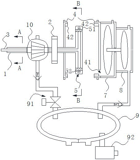
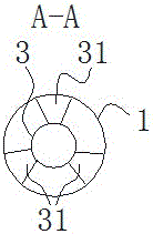
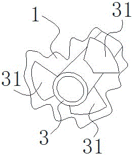
[0050] Such as Figure 1-Figure 5 As shown, a turbine includes a wheel shaft 1, a power output wheel 2, a casing 4 and a wheel disc 5, the wheel disc 5 is arranged inside the casing 4, and the wheel shaft 1 rotatably runs through the casing 4 and the end is fixedly connected to the center of the wheel disc 5, the power output wheel 2 is arranged on the wheel shaft 1 and is used for outputting power;

[0051] The casing 4 and the roulette 5 are cylindrical as a whole;

[0052] The wheel disc 5 is a hollow structure and thereby forms an inner cavity, the wheel shaft 1 is a tubular structure, and the wheel disc 5 and the end of the wheel shaft 1 are connected through and fixed to form a rotor body of the turbine;

[0053] The outer surface of the wheel disc 5 is evenly provided with a plurality of hollow gear teeth 51 extending along t...


PUM


Abstract

The invention provides a novel turbine. The novel turbine comprises a wheel shaft, a power output wheel, a housing and a wheel disc. The wheel shaft and the wheel disc are hollow structures fixed and communicated with each other and form a rotor body of the turbine. The outer surface of the wheel disc is uniformly provided with multiple hollow gears along a circumferential direction, the hollow gears extends along a tangential direction and gear openings are turbine nozzles. The housing is provided with an exhaust channel with an exhaust valve. The inner wall of the housing is uniformly provided with multiple raised lines extending along an axial direction. The top of each one of the raised lines and the tops of the wheel tooth form slidable seal contact so that a supercharging propulsion chamber is arranged between the two adjacent rotary gears in the housing. The novel turbine effectively solves the problem of turbine pressure loss-caused energy loss, prevents influence on blades in a high temperature and high pressure environment and prolongs a wheel disc service life.

Description

technical field [0001] The present invention relates to a turbine applicable to gas-air mixture, water or steam. Background technique [0002] A turbine is a rotating power machine that converts the energy of a gas (gas or steam) or liquid into mechanical work. A turbine or an internal combustion engine are both types of turbines. [0003] In the current prior art, the publication number is CN103953488, and the technical scheme named "recoil impeller engine" includes energy through the energy supply device, the running sealing mechanism, the impeller, and the nozzle spraying out along the centrifugal tangent angle of the impeller to supply energy. The cross-sectional area of ​​the device is greater than the sum of the cross-sectional areas of several nozzles, and the cross-sectional area of ​​the nozzle is greater than the cross-sectional area of ​​the nozzle; the energy of the recoil impeller engine water, steam, and gas is converted into the injection kinetic energy of th...

Claims


Application Information

Patent Timeline
Patent Type & Authority Patents(China)
IPC IPC(8): F02C3/00F01D1/32F03B1/00
CPCY02E10/20
Inventor 邓小波
Owner 邓小波
Why Eureka
Try Eureka