
Composite material plate spring

A composite plate, consistent technology, applied in the direction of springs, springs/shock absorbers, spring assemblies composed of several springs, etc., can solve the problems of easy convergence of cracks, easy cracks, short fatigue life of composite plate springs, etc. , to achieve the effect of improving fatigue life, increasing strength, and high level of lightweight

Active Publication Date: 2015-10-07
JILIN UNIV +1
View PDF7 Cites 4 Cited by
  • Summary
  • Abstract
  • Description
  • Claims
  • Application Information

AI Technical Summary

Problems solved by technology

[0005] Although scholars at home and abroad have done a lot of research on composite leaf springs for automobiles, there are still few studies on composite leaf springs with parabolic shapes, and the fatigue process of existing parabolic shaped composite leaf springs is relatively long and short. Cracks are easy to occur at the junction of layers, and the generated cracks are easy to merge, which will cause the peeling and delamination of the composite leaf spring, resulting in short fatigue life of the composite leaf spring

Method used


Image

  • Composite material plate spring
  • Composite material plate spring
  • Composite material plate spring

Examples


Embodiment 1

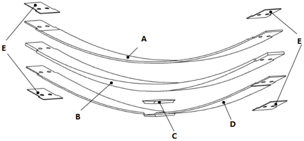
[0037] Such as image 3 As shown, it is the shape structure of the composite material leaf spring in this embodiment, and the number of layers is 59 layers. Except for the E area, the arrangement of each layer is based on the midpoint of the length direction of each layer as the reference point, and through the finite element Modeling analysis, extracting the stress distribution data of the cross-section where each longer ply and shorter ply are connected.

[0038] Such as Figure 4 As shown, the length of each layer in area A is 1359 mm, and the number of layers is 7 layers; the length of the longest layer in area B is 1359 mm, the number of layers is 11 layers, and the number of layer layers with gradient length is 21 layers; C There are 10 short plies used to form the boss structure in the area; the length of each ply in area D is 1385mm, and the number of plies is 6; there are 4 layers of plain cloth ply in area E, which are distributed in the bolt holes of the end joints...


PUM


Abstract

The invention belongs to the field of plate springs, and particularly relates to a composite material plate spring. A spring body is in a parabola shape, and a boss structure is arranged in the middle of the spring body. Laying layers of the composite material plate spring are divided into an area A, an area B, an area C, an area D and an area E from top to bottom. Equilong long laying layers of a certain layer number are arranged in the area A and the area D. Equilong long laying layers and laying layers with gradually-changing length of a certain layer number are arranged in the area B, the long laying layers and the short laying layers are arranged alternately, and a genetic algorithm is adopted in the area B to optimize the sequence of the laying layers. The area C is of a boss structure formed by short laying layers of a certain layer number. Plain cloth laying layers of a certain layer number are arranged in the area E. The fiber arrangement direction of all the laying layers in the area A, the area B and the area D is consistent with the longitudinal direction of the spring body of the composite material plate spring. The composite material plate spring has the advantages that the spring is light, no hole needs to be drilled in the middle, the fatigue life is prolonged, and the strength of an end connector is improved.

Description

technical field [0001] The invention belongs to the field of leaf springs, in particular to a composite material leaf spring applied to automobile suspension. Background technique [0002] As a technology-intensive industry, the rapid development of the automobile industry is inseparable from the research and development of new materials and processes. As people's requirements for lightweight automobiles become higher and higher, materials such as steel and alloys used in automobile parts begin to gradually Replaced by lightweight composite materials. Resin-based composite materials, including glass fiber-reinforced resin-based composite materials and carbon fiber-reinforced resin-based composite materials, have the characteristics of light weight, high strength, designable performance, good corrosion resistance, strong vibration damping, easy molding and simple process. , and its fatigue limit is relatively high, and its sensitivity to stress concentration is small, so it ...

Claims


Application Information

Patent Timeline
Patent Type & Authority Applications(China)
IPC IPC(8): F16F1/18F16F3/00
CPCF16F1/18F16F3/00
Inventor 史文库钱琛柯俊李国民周刚
Owner JILIN UNIV
Learn More