Liquid hydrogen source material dehydrogenation reaction system and application method thereof

A reaction system and liquid hydrogen technology, applied in the field of organic liquid hydrogen storage, can solve the problems of hydrogen content, poisoning fuel cells, and inability to achieve large-scale application.

Active Publication Date: 2015-10-14
WUHAN HYNERTECH CO LTD
View PDF4 Cites 14 Cited by
  • Summary
  • Abstract
  • Description
  • Claims
  • Application Information

AI Technical Summary

Problems solved by technology

The liquid organic hydrogen storage material developed in Germany can realize the hydrogen absorption/desorption cycle under relatively mild conditions, but there are important defects such as the hydrogen released by the hydrogen storage material containing gas poisonous to the fuel cell and inconvenient

Method used


Image

  • Liquid hydrogen source material dehydrogenation reaction system and application method thereof
  • Liquid hydrogen source material dehydrogenation reaction system and application method thereof

Examples


Embodiment 1

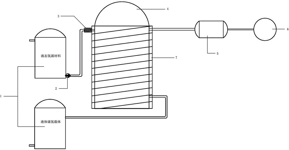
[0048] Such as figure 1 As shown, the storage equipment is a storage tank, and the liquid hydrogen source material and the liquid hydrogen storage carrier are respectively stored in different storage tanks 1, and each storage tank is respectively provided with an input port and an output port. A pump 2 is arranged at the output port of the reactor, and a preheating device 3 is arranged on the outside of the input pipe connecting the pump and the reactor, and the preheating device is an electric heating device. The liquid hydrogen source material is fed into the reactor 4 by the operation of the pump. The reactor is a tower reactor filled with a dehydrogenation catalyst. The liquid hydrogen source material is decomposed into hydrogen gas and liquid hydrogen storage carrier in the reactor, and the hydrogen storage carrier is transported back to the space where the hydrogen storage carrier is stored. The hydrogen gas is sent to the buffer tank 5 and from there to the fuel cell ...

Embodiment 2

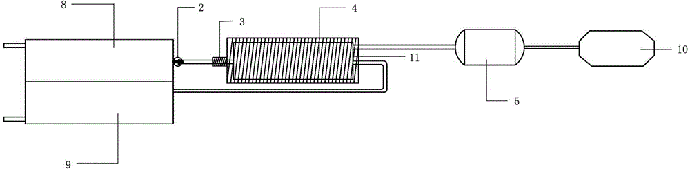
[0050] Such as figure 2 As shown, the storage device is a vehicle-mounted storage tank, and the storage tank is provided with spaces for storing the liquid hydrogen source material liquid and the hydrogen storage carrier respectively: a first storage room 9 and a second storage room 10, and the first and second storage rooms are respectively provided with Input port and output port. The output port of the first storage chamber is provided with a pump 2, and the input pipe connecting the pump and the reaction kettle is provided with a preheating device 3 outside, and the preheating device is an electric heating device powered by a storage battery. The liquid hydrogen source material is fed into the reactor 4 by the operation of the pump. The reactor is a plate reactor filled with a dehydrogenation catalyst. The liquid hydrogen source material is decomposed into hydrogen gas and liquid hydrogen storage carrier in the reactor, and the liquid hydrogen storage carrier is transpo...

Embodiment 3

[0052] The storage device is a miniature storage tank, and the storage tank is provided with spaces for storing liquid hydrogen source materials and hydrogen storage carriers: a first storage room and a second storage room, and the first and second storage rooms are respectively provided with an input port and an output port. The output port of the first storage chamber is provided with a pump.

[0053] The liquid hydrogen source material is input into the pipeline heat transfer equipment installed outside the hydrogen internal combustion engine through a pump, and the heat generated by the hydrogen internal combustion engine is transferred to the reactor through the heating device, and then enters the reactor for dehydrogenation reaction. The reactor is a tubular reactor. , filled with a dehydrogenation catalyst. The liquid hydrogen source material is decomposed into hydrogen gas and hydrogen storage carrier in the reactor, and the hydrogen storage carrier is transported back...


PUM


Abstract

The invention discloses a liquid hydrogen source material dehydrogenation reaction system and an application method thereof. The dehydrogenation system comprises a storage device used for storing a liquid hydrogen source material and a liquid hydrogen-storage carrier, a reaction kettle used for dehydrogenating the liquid hydrogen source material, a buffering tank used for storing hydrogen gas, and a heating device arranged outside the reaction kettle and used for heating the reaction kettle. According to the invention, the liquid hydrogen source material is delivered into the reaction kettle through a pump; the liquid hydrogen source material is dehydrogenated in the reaction kettle; produced hydrogen gas is delivered to the buffering tank; and residual liquid hydrogen-storage carrier is delivered back to the hydrogen storage tank. The normal-temperature normal-pressure liquid hydrogen source material dehydrogenation system provided by the invention is used for carrying out a dehydrogenation reaction upon the liquid hydrogen source material. The produced hydrogen gas is supplied for a fuel cell or an internal combustion engine. The hydrogen gas is converted into electrical energy or mechanical energy which can be applied in various industrial and civil fields such as automobiles, electrical power, energy storage, chemical engineering, pharmacy, and mobile devices.

Description

technical field [0001] The invention relates to the technical field of organic liquid hydrogen storage, in particular to a dehydrogenation system of a liquid hydrogen source material at normal temperature and pressure and a method for using the same. Background technique [0002] The development of new energy sources to replace or partially replace non-renewable fossil fuels is one of the greatest challenges facing mankind in this century. In the "Twelfth Five-Year" National Strategic Emerging Industry Development Plan promulgated by the State Council last year, new energy and new energy vehicles represented by hydrogen energy fuel cells were listed separately as key development industries, and a clear development goals and routes. Due to its wide source of raw materials, pollution-free and high energy conversion efficiency, hydrogen energy is the preferred new energy technology to solve the future demand for clean energy. [0003] Hydrogen energy technology includes large...

Claims


Application Information

Patent Timeline
IPC IPC(8): C01B3/02C07B35/04
Inventor 程寒松程健林安管一龙
Owner WUHAN HYNERTECH CO LTD
Why Eureka
Try Eureka