
Exhaust manifold device and front end cover processing method

A technology of exhaust manifold and front end cover, which is applied in the direction of exhaust device, muffler device, metal processing equipment, etc. It can solve the problems of cylinder exhaust turbulence, reduce exhaust resistance, improve utilization rate and service life, The effect of improving power

Active Publication Date: 2015-10-14
BRILLIANCE AUTO
View PDF7 Cites 0 Cited by
  • Summary
  • Abstract
  • Description
  • Claims
  • Application Information

AI Technical Summary

Problems solved by technology

[0003] The invention proposes an exhaust manifold device and a processing method for the front end cover, which solves the problems of cylinder exhaust turbulence and eddy current in the existing exhaust manifold, and has a simple structure, reasonable design and convenient manufacture

Method used


Image

  • Exhaust manifold device and front end cover processing method
  • Exhaust manifold device and front end cover processing method
  • Exhaust manifold device and front end cover processing method

Examples


Embodiment 1

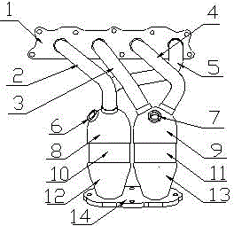
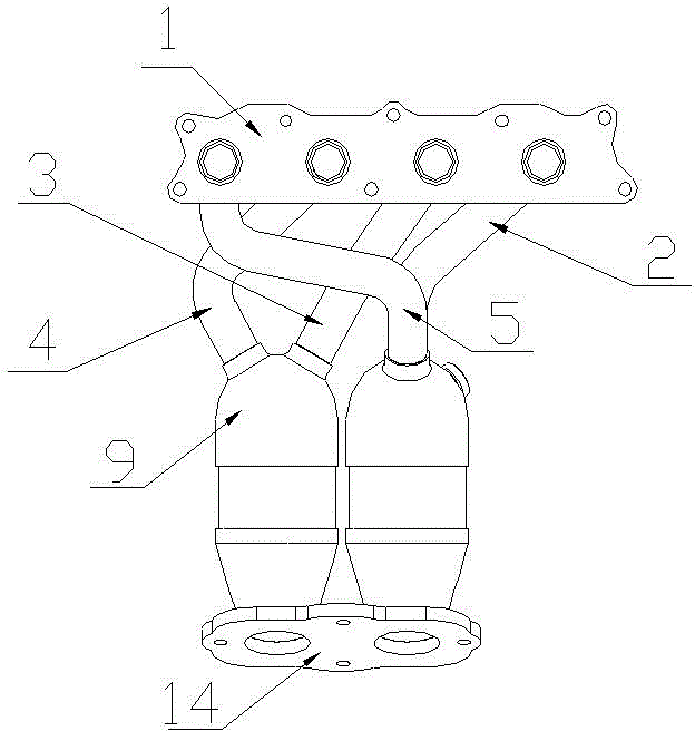
[0021] The exhaust manifold device adopted in this embodiment includes an inlet flange 1, an outlet flange 14 and an elbow exhaust channel connected with the cylinder fixed between the two, including the first elbow air channel 2, the second The elbow air channel 3, the third elbow air channel 4 and the fourth elbow air channel 5, the first catalytic converter front end cover 8, the first catalytic converter body 10 and the first catalytic converter rear end cover sequentially connected together 12, the second catalytic converter assembly is composed of the second catalytic converter front end cover 9, the second catalytic converter body 11 and the second catalytic converter rear end cover 13 which are sequentially connected together. Wherein, the elbow exhaust ports are connected together in groups of two according to the firing sequence of the cylinders at intervals, for example, the first elbow air port 2 and the fourth elbow air port 5 are connected together to form the fir...

Embodiment 2

[0025] A method for processing the front end cover of an exhaust manifold, processing the front end cover, comprising the following steps:

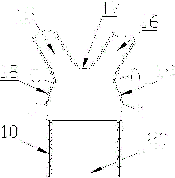
[0026] Step 1: Use Pro / Engineer software or CATIA v5 to establish a 3D model of the front cover, including the first air inlet, the second air inlet, the first drainage part at the connection between the first air inlet and the second air inlet, and The second arc-shaped drain connected to the first air inlet, the third arc-shaped drain connected to the third arc-shaped drain, and the front end cover body connected to the second arc-shaped drain and the third arc-shaped drain. In this embodiment, it is assumed that the initial arc radii of the second arc-shaped drain portion CD and the third arc-shaped drain portion AB are the same as the radius of the catalytic converter body, both being 50 mm. Users can set according to their needs.

[0027] Step 2: Use fluid mechanics to calculate the fluid distribution on the front surface of the cer...


PUM


Abstract

The invention relates to the technical field of exhaust devices of internal combustion engines, in particular to an exhaust manifold device and a front end cover processing method. Every two bend exhaust channels are connected together as a set in a spaced air cylinder ignition sequence. Through the structure of adopting every two bend air channels as a set in an ignition spacing mode, the poor phenomena of airflow snatching, backflow and the like are avoided; exhaust resistance is effectively reduced; the dynamic property is improved. Gas data recognized by two oxygen sensors are more accurate, reasonable parameters are provided for fuel oil injection, and more oil is saved. Due to the fact that the bend air channels form a Y-shaped structure, and catalyst front end covers comprise first air inlets, second air inlets, first drainage parts, second arc-shaped drainage parts and third arc-shaped drainage parts, airflow is made to be evenly mixed through the unique arc-shaped structure; the utilization rate of catalytic agents is effectively improved, and the service life of the catalytic agents is effectively prolonged. Finally, two catalysts connected in parallel are used for improving conversion capacity and catalytic efficiency, and the exhaust level is improved.

Description

technical field [0001] The invention relates to the technical field of exhaust devices of internal combustion engines, in particular to an exhaust manifold device and a processing method for a front end cover. Background technique [0002] With the increasingly stringent requirements of automobile emission standards and people's higher pursuit of vehicle power and economy, for the exhaust manifold and catalytic converter of an in-line 4-cylinder four-stroke engine, the existing technology usually uses the The structure in which the four exhaust passages converge into the same catalytic converter can easily cause exhaust turbulence and swirl in each cylinder, which increases exhaust resistance and reduces power performance. At the same time, since the four airways each use a single oxygen sensor, the information identified by the oxygen sensor is not accurate enough, resulting in high fuel consumption. In addition, traditional technologies often increase the emission level b...

Claims


Application Information

Patent Timeline
IPC IPC(8): F01N13/10F01N3/28B21D37/20G06F17/50
Inventor 贺永刚黄昌瑞李振华李志广
Owner BRILLIANCE AUTO
Features
  • Generate Ideas
  • Intellectual Property
  • Life Sciences
  • Materials
  • Tech Scout
  • Unparalleled Data Quality
  • Higher Quality Content
  • 60% Fewer Hallucinations
Learn More