Vapor Chamber with Structure having capillary force

A technology of capillary force and vapor chamber, applied in laboratory appliances, indirect heat exchangers, lighting and heating equipment, etc., can solve problems such as small ratio of length to width of attachment area, limitation of evaporation and heat dissipation, performance degradation of vapor chamber, etc. To achieve the effect of improving heat dissipation and cooling function, increasing the contact area, and increasing the contact area

Inactive Publication Date: 2015-10-14
金兴倍
View PDF8 Cites 24 Cited by
  • Summary
  • Abstract
  • Description
  • Claims
  • Application Information

AI Technical Summary

Problems solved by technology

Brackets can be set separately on the upper / lower plates as needed, thus resulting in increased thickness of the vapor chamber, resulting in it not being thin enough
[0007] Second, the limitations of carbon gold plating in the vapor chamber
In addition, if carbon gold plating is attached to a large area, the performance of the vapor chamber will decrease, so there is also a limit to the area of ​​carbon gold plating.
The limitation of the carbon gold-plated attachment area results in a relatively small aspect ratio of the attachment area, and the heat in the vapor chamber will boil, and the function of evaporation and heat dissipation is limited.

Method used


Image

  • Vapor Chamber with Structure having capillary force
  • Vapor Chamber with Structure having capillary force
  • Vapor Chamber with Structure having capillary force

Examples


Embodiment Construction

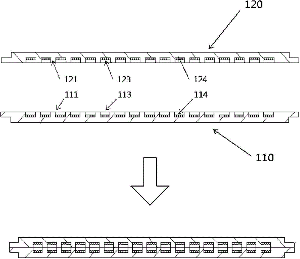
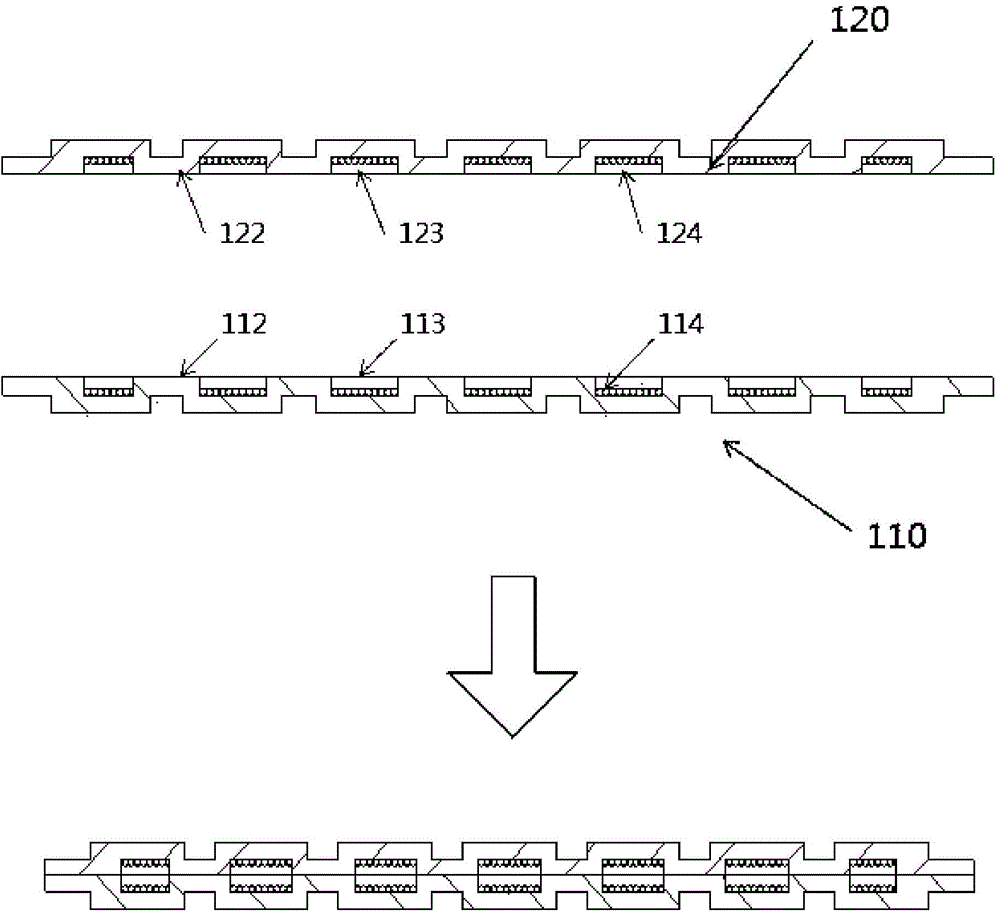
[0048]The technical features of this invention are as follows: the lower plate and the upper plate form a soaking plate, and grooves or grooves are formed on the lower plate and the upper plate. On the channels formed between grooves or grooves, a porous substance is formed due to the accumulation of layers of metal powder. After being chemically filtered and then solidified, the layers of metal powder are stacked to form a porous structure. These porous structures make the capillary force develop rapidly, and the cooling performance of the capillary force is also significantly improved, and portable electronic products can dissipate heat more effectively.

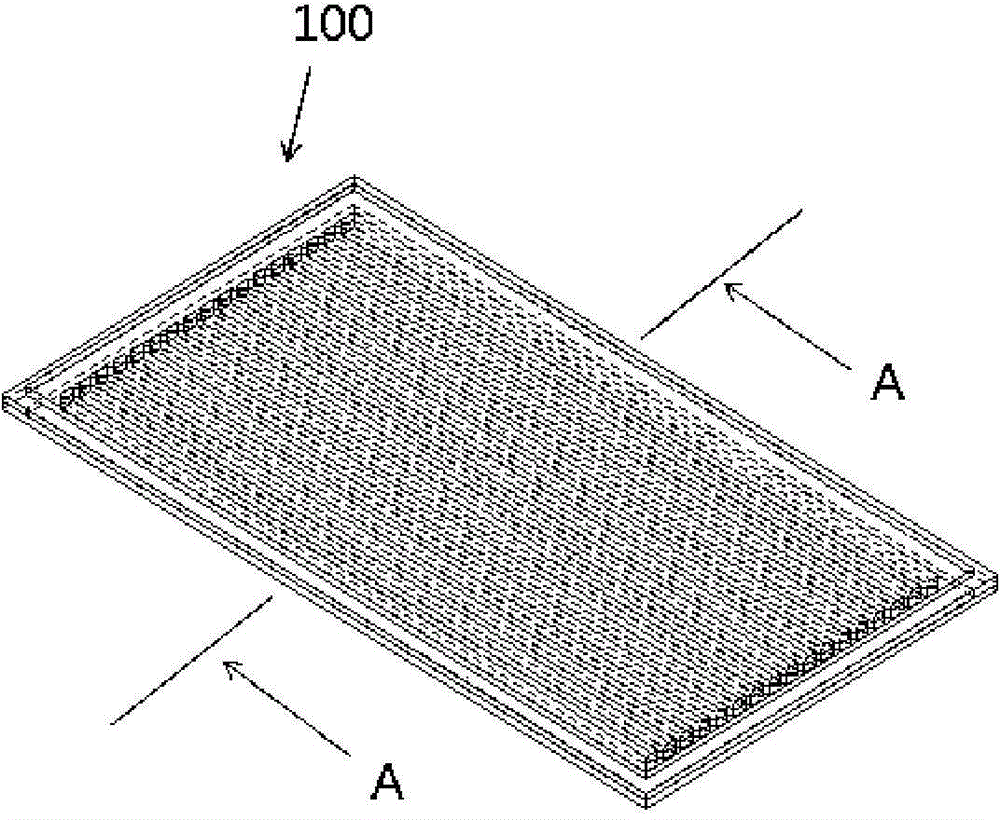
[0049] refer to figure 1 and figure 2 , the embodiment of the present invention provides a vapor chamber formed by a structure with capillary force, which is composed of a lower plate 110 and an upper plate 120, and liquid oil is injected between the upper and lower plates to achieve a vacuum-tight state, thereby mainta...


PUM


Abstract

The present invention relates to a vapor chamber including a structure with a capillary force and, more particularly, to a vapor chamber including a structure with a capillary force capable of remarkably improving cooling performance by efficiently discharging heat generated in a portable electronic device with the great improvement of the capillary force by stacking metal powder with porosity through hardening after separation with a chemical method by stacking the metal powder on a porous structure when the porous structure is formed in a path between grooves or channels by forming a vapor structure to smooth the flow of an operating fluid in a longitudinal direction by forming the grooves or the channels on a top plate and a bottom plate comprising the chamber.

Description

technical field [0001] The present invention is a vapor chamber formed of a structure with capillary force. Specifically, grooves or grooves are formed on the upper plate and the lower plate constituting the heating plate to form an evaporation structure for smoother flow process, and a porous structure is formed on the channels formed between the grooves or grooves. This porous structure stacks the metal powder layer by layer, and after filtering out by chemical methods, the metal powder is made porous through solidification technology, which greatly improves the capillary force, helps portable electronic instruments to dissipate heat more effectively, and significantly improves their cooling. sex. Background technique [0002] Ordinary electronic products are designed to perform their functions at room temperature, so if the heat generated by electronic products cannot be dissipated in time, the electronic products will be overheated and their functions will be significan...

Claims


Application Information

Patent Timeline
Patent Type & Authority Applications(China)
IPC IPC(8): F28D15/04
CPCB01L3/5027B01L2400/0406H05K7/20409
Inventor 金兴倍
Owner 金兴倍
Why Eureka
Try Eureka