
Camera, remote control system and remote control method

A remote control system and camera technology, applied in the field of cameras, to achieve the effect of reducing the cost and complexity of wiring harnesses, reducing volume and cost

Inactive Publication Date: 2015-10-14
TUNG THIH ELECTRONICS
View PDF3 Cites 2 Cited by
  • Summary
  • Abstract
  • Description
  • Claims
  • Application Information

AI Technical Summary

Problems solved by technology

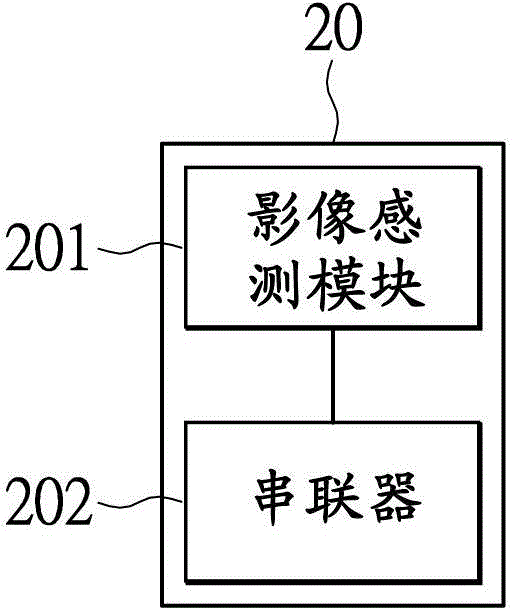
The camera includes a serializer and an image sensor module

Method used


Image

  • Camera, remote control system and remote control method
  • Camera, remote control system and remote control method
  • Camera, remote control system and remote control method

Examples


Embodiment Construction

[0029] Various exemplary embodiments will be described more fully hereinafter with reference to the accompanying drawings, in which some exemplary embodiments are shown. However, inventive concepts may be embodied in many different forms and should not be construed as limited to the illustrative embodiments set forth herein. Rather, these exemplary embodiments are provided so that this disclosure will be thorough and complete, and will fully convey the scope of the inventive concept to those skilled in the art. In the drawings, the size and relative sizes of layers and regions may be exaggerated for clarity. Like numbers indicate like components throughout.

[0030] It will be understood that although the terms first, second, third etc. may be used herein to describe various components, these components should not be limited by these terms. These terms are used to distinguish one component from another. Thus, a first component discussed below could be termed a second compon...


PUM


Abstract

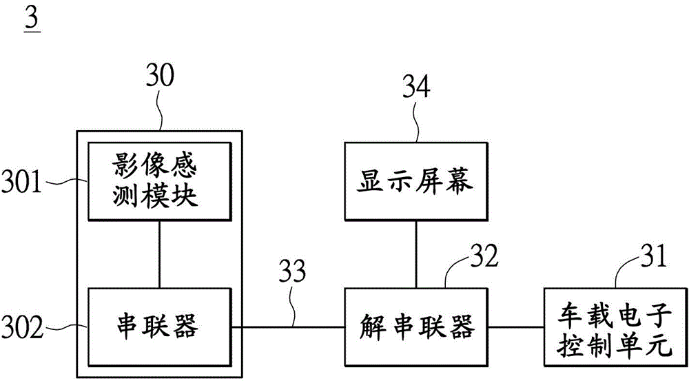
The invention provides a camera, a remote control system and a remote control method. The camera comprises a serializer and an image sensing module. The serializer is connected to a low voltage differential signal cable, and the serializer receives a control signal through the low voltage differential signal cable. The image sensing module is coupled to the serializer and is used for sensing an automobile surrounding according to the control signal, generating an image signal and transmitting the image signal to the serializer. When transmitting the image signal to the serializer, the image sensing module serializes the image signal into a sequence signal and outputs the sequence signal through the low voltage differential signal cable.

Description

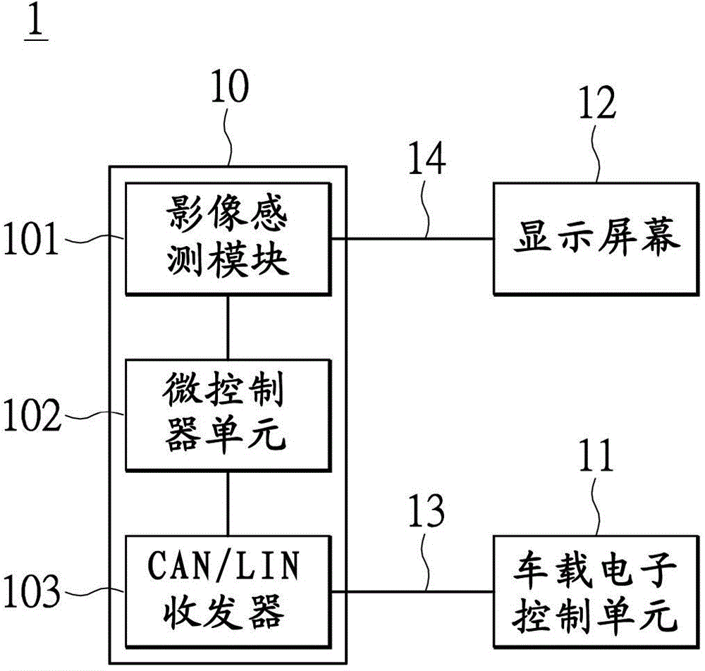
technical field [0001] The present invention relates to a camera, and in particular to a camera mounted on a car, a remote control system and a control method thereof. Background technique [0002] A camera is an electronic device that is often installed in a car today. It can sense and capture images around the vehicle body to reduce blind spots for the driver, thereby improving driving safety and assisting driving. [0003] see figure 1 , figure 1 It is a schematic diagram of the architecture of a traditional remote control system. A traditional remote control system 1 includes a camera 10, a vehicle-mounted electronic control unit 11 (Electronic Control Unit, ECU), a display screen 12, and a controller area network / local link network (Controller Area Network / Local Interconnect Network, referred to as CAN / LIN) Cable 13 and image signal transmission line 14. [0004] The camera 10 includes an image sensor module 101 (Image Sensor), a microcontroller unit 102 (Microcontr...

Claims


Application Information

Patent Timeline
Patent Type & Authority Applications(China)
IPC IPC(8): H04N5/232H04N7/18
Inventor 韩颖伦洪涣淋蔡春英
Owner TUNG THIH ELECTRONICS
Learn More