Compound dust collector for boilers

A dust removal device and composite technology, which is applied in the direction of combined devices, dispersed particle separation, chemical instruments and methods, etc., can solve problems such as difficult to achieve dust removal and purification effects, secondary water pollution, and impact on environmental quality, and achieve good flue gas dust removal Purification effect, prevention of secondary water pollution, effect of reducing smog

Active Publication Date: 2015-10-21
HMEI THREAD CO LTD OF YINBIN SICHUAN
View PDF7 Cites 1 Cited by
  • Summary
  • Abstract
  • Description
  • Claims
  • Application Information

AI Technical Summary

Problems solved by technology

[0004] Although the desulfurization and dedusting composite tower disclosed in this patent document can dedust the flue gas to a certain extent, due to the unreasonable structural design, the ash-water mixture caused by the flushing device is likely to cause secondary water pollution, affecting environmental quality, and through static electricity Dust removal can only absorb most of the dust-containing flue gas, and its fine ash particles will slip away with the flue gas, making it difficult to achieve effective dust removal and purification effects

Method used


Image

  • Compound dust collector for boilers
  • Compound dust collector for boilers
  • Compound dust collector for boilers

Examples


Embodiment 1

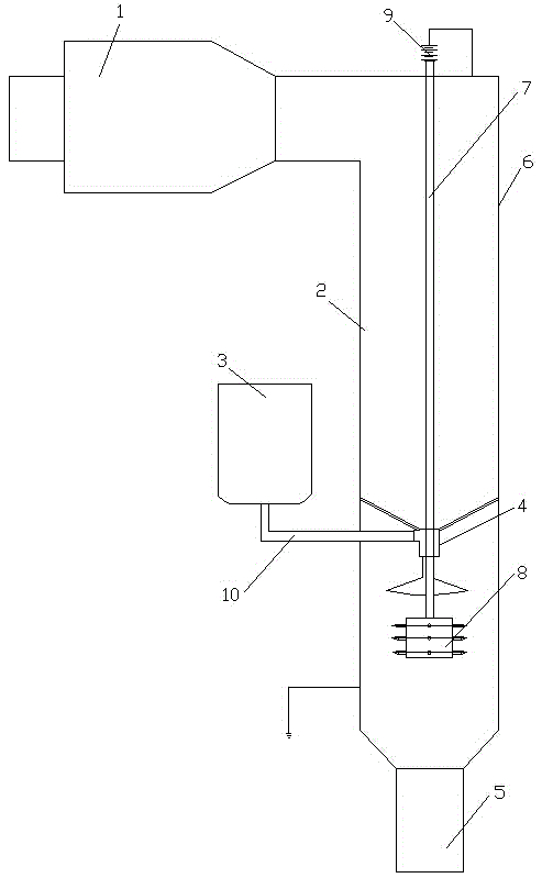
[0036] see figure 1, a composite dedusting device for a boiler, including an electrostatic precipitator 1 connected to the boiler flue, and also includes a shaft electric field 2, an alkali tank 3, a sprayer 4 and an evaporation drying box 5, and the shaft electric field 2 is composed of a shaft 6. The conductive rod 7, the electrode 8 located in the shaft 6 and the high-voltage electrostatic power supply 9 outside the shaft 6 are formed. The positive pole of the high-voltage electrostatic power supply 9 is connected to the outer wall of the shaft 6 through a wire, and the negative pole is connected to the electrode 8 through the conductive rod 7. The lye tank 3 is located outside the shaft 6, the sprayer 4 is located in the shaft 6, the sprayer 4 is arranged above the electrode 8, the sprayer 4 is connected with the lye tank 3 through the liquid spray pipe 10, and the evaporation drying box 5 is connected to the shaft The bottom of shaft 6 is connected, and the top of vertica...

Embodiment 2

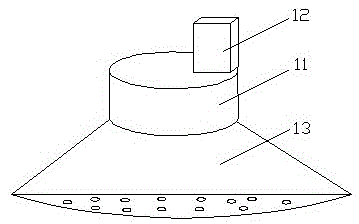
[0039] see figure 1 and figure 2 , a composite dedusting device for a boiler, including an electrostatic precipitator 1 connected to the boiler flue, and also includes a shaft electric field 2, an alkali tank 3, a sprayer 4 and an evaporation drying box 5, and the shaft electric field 2 is composed of a shaft 6. The conductive rod 7, the electrode 8 located in the shaft 6 and the high-voltage electrostatic power supply 9 outside the shaft 6 are formed. The positive pole of the high-voltage electrostatic power supply 9 is connected to the outer wall of the shaft 6 through a wire, and the negative pole is connected to the electrode 8 through the conductive rod 7. The lye tank 3 is located outside the shaft 6, the sprayer 4 is located in the shaft 6, the sprayer 4 is arranged above the electrode 8, the sprayer 4 is connected with the lye tank 3 through the liquid spray pipe 10, and the evaporation drying box 5 is connected to the shaft The bottom of shaft 6 is connected, and th...

Embodiment 3

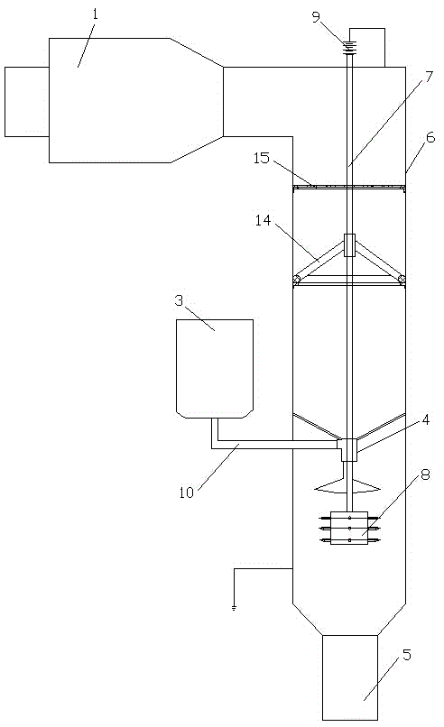
[0043] Reference figure 2 and image 3 , a composite dedusting device for a boiler, including an electrostatic precipitator 1 connected to the boiler flue, and also includes a shaft electric field 2, an alkali tank 3, a sprayer 4 and an evaporation drying box 5, and the shaft electric field 2 is composed of a shaft 6. The conductive rod 7, the electrode 8 located in the shaft 6 and the high-voltage electrostatic power supply 9 outside the shaft 6 are formed. The positive pole of the high-voltage electrostatic power supply 9 is connected to the outer wall of the shaft 6 through a wire, and the negative pole is connected to the electrode 8 through the conductive rod 7. The lye tank 3 is located outside the shaft 6, the sprayer 4 is located in the shaft 6, the sprayer 4 is arranged above the electrode 8, the sprayer 4 is connected with the lye tank 3 through the liquid spray pipe 10, and the evaporation drying box 5 is connected to the shaft The bottom of shaft 6 is connected, ...


PUM


Abstract

The invention discloses a compound dust collector for boilers. The compound dust collector comprises an electrostatic deduster connected to the flue of a boiler, and also comprises a shaft well electric field, an alkali solution tank, a sprayer and an evaporation drying box, the shaft well electric field is formed by a shaft well, a conductive rod, an electrode positioned in the shaft well and a high-voltage electrostatic power supply positioned outside the shaft well, the positive electrode of the high-voltage electrostatic power supply is connected with the outer wall of the shaft well through a lead, the negative electrode of the power supply is connected with the electrode through the conductive rod, the alkali solution tank is positioned outside the shaft well, the sprayer is arranged in the shaft well, the sprayer is arranged above the electrode, the sprayer is connected with the alkali solution tank through a solution spraying tube, the evaporation drying box is connected with the bottom of the shaft well, and the top of the shaft well is connected with the electrostatic deduster. The compound dust collector can maximally remove ash particles in flue gas, reduce haze in air and remove sulfur dioxide in the flue gas, also can effectively prevent secondary water pollution caused by ash and water mixture, and realizes a good flue gas dedusting and purifying effect.

Description

technical field [0001] The invention relates to the technical field of dust removal and purification of boiler flue gas, in particular to a composite dust removal device for boilers. Background technique [0002] Coal-fired boilers used in thermal power plants, industrial boilers, heating boilers, and kilns fueled by coal in iron and steel enterprises will emit a large amount of flue gas into the atmosphere. There are a large amount of sulfur dioxide, nitrogen oxides and dust in the flue gas, which are toxic. The substances are also discharged to the atmosphere with the flue gas, which is the main source of air pollution. Although the efficiency of conventional electrostatic precipitators has reached 99%, its dust removal efficiency is still very low for too fine dust; Dust has high efficiency, but the resistance is very large, and it consumes a lot of electric energy. It is incompatible with the current situation of energy saving and emission reduction, and there are very f...

Claims


Application Information

Patent Timeline
Patent Type & Authority Applications(China)
IPC IPC(8): B01D50/00B01D53/50B01D53/78
Inventor 肖雪峰蒋文斌冯静张西平
Owner HMEI THREAD CO LTD OF YINBIN SICHUAN
Why Eureka
Try Eureka