
Bender of steel-wire mesh

A steel mesh and bending machine technology, applied in the field of steel mesh bending machines, can solve the problems of low precision, inability to meet use requirements, low efficiency, etc., and achieve the effects of high processing efficiency, stable shape, and high forming precision.

Active Publication Date: 2015-10-21
四川鸥克建材科技有限公司
View PDF5 Cites 7 Cited by
  • Summary
  • Abstract
  • Description
  • Claims
  • Application Information

AI Technical Summary

Problems solved by technology

At present, there is no professional equipment for bending and forming steel wire mesh. If manual bending is used, the efficiency and precision are low, and it cannot meet the requirements of use.

Method used


Image

  • Bender of steel-wire mesh
  • Bender of steel-wire mesh
  • Bender of steel-wire mesh

Examples


Embodiment Construction

[0038] The present invention will be further described below in conjunction with the accompanying drawings and embodiments.

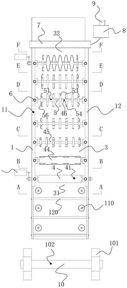
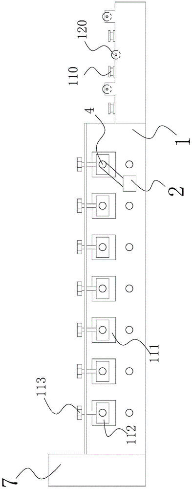
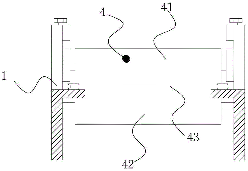
[0039] Such as Figure 1 to Figure 8As shown, in the wire mesh bending machine of the present invention, the frame 1 includes a first side support plate 11 and a second side support plate 12 parallel to each other, and the first side support plate 11 and the second side support plate 12 Form forming channel 3; One end of described forming channel 3 is steel wire mesh feed end 31, and the other end is steel wire mesh discharge end 32; In the forming channel 3 from steel wire mesh feed end 31 to steel wire mesh discharge end 32, At least one pair of power rollers 4 and multiple pairs of forming rollers 5 for driving the wire mesh to advance are provided in sequence, and the two ends of the power rollers 4 are respectively rotatably matched with the first side support plate 11 and the second side support plate 12; The two ends of the forming roller 5 are ...


PUM


Abstract

The invention, which relates to the field of the steel-wire mesh processing equipment, provides a bender of a steel-wire mesh. The bender comprises a rack and a power unit. The rack includes a first side support plate and a second side support plate; and a moulding channel is encircled by the first side support plate and the second side support plate. One end of the moulding channel is feeding end of a steel-wire mesh and the other end is a discharging end of the steel-wire mesh. Power rollers and moulding rollers are successively arranged from the steel-wire mesh feeding end and the steel-wire mesh discharging end; the power rollers and the moulding rollers and the first side support plate and the second side support plate are in rotating cooperation mode. A steel-wire mesh feeding channel is formed between the upper power roller and the lower power roller of each pair of power rollers; and an upper pressing wheel and a lower pressing wheel is arranged at each pair of moulding rollers. At the marching direction of the steel-wire mesh, the external diameter of the upper pressing wheel and the external diameter of the lower pressing wheel are increased successively; and the distance between the each two adjacent two lower pressing wheels is reduced. The power unit and the power rollers are in transmission connection. According to the bender, the multiple moulding rollers are bent step by step for moulding; the moulding precision is high; continuous bending is realized; and the processing efficiency is high.

Description

technical field [0001] The invention relates to the field of steel wire mesh processing equipment, in particular to a steel wire mesh bending machine. Background technique [0002] In the pouring construction of concrete wall panels, in order to improve the strength of concrete wall panels, steel wire mesh can be added during pouring. In order to make the steel mesh have a stronger bearing capacity, it is necessary to bend the steel mesh to make its section wavy before pouring construction. At present, there is no professional equipment for bending and forming steel wire mesh. If manual bending is used, the efficiency and precision are low, which cannot meet the requirements of use. Contents of the invention [0003] The technical problem to be solved by the present invention is to provide a wire mesh bending machine capable of bending the wire mesh to a desired shape. [0004] The technical solution adopted by the present invention to solve its technical problems is: a ...

Claims


Application Information

Patent Timeline
Patent Type & Authority Applications(China)
IPC IPC(8): B21D11/12
CPCB21D11/125
Inventor 许迪茗党清泉
Owner 四川鸥克建材科技有限公司
Learn More