Method for improving hydrogen recovery rate

A recovery rate and hydrogen technology, applied in hydrogen separation, using solid contact hydrogen separation, etc., can solve the problems of large investment and high energy consumption in cryogenic separation

Active Publication Date: 2015-10-21
SOUTHWEST RES & DESIGN INST OF CHEM IND
View PDF3 Cites 8 Cited by
  • Summary
  • Abstract
  • Description
  • Claims
  • Application Information

AI Technical Summary

Problems solved by technology

The cryogenic separation method requires large investment and high energy consumption, and is not suitable for small and medium-scale refinery gas recovery of hydrogen

Method used


Image

  • Method for improving hydrogen recovery rate
  • Method for improving hydrogen recovery rate
  • Method for improving hydrogen recovery rate

Examples


Embodiment 1

[0035] Raw gas composition

[0036] FCC dry gas

[0037] composition

H 2

CH 4

C 2

C 3

C 4

CO

CO 2

O 2

N 2

V%

45.00

15.50

14.33

1.40

0.25

1.29

3.38

0.45

18.4

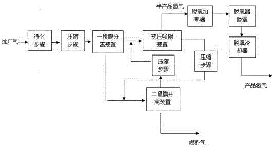
[0038] The feed gas is firstly dewatered by the gas-liquid separator under the pressure of ~1.5MPa, and then enters a membrane separation device.

[0039] One-stage membrane separation device: hydrogen gas passes through the membrane to form permeate gas (hydrogen-containing gas), and the hydrogen-containing gas enters the pressure swing adsorption device for pressure swing adsorption hydrogen separation. The retentate gas that fails to pass through the membrane directly enters the second-stage membrane separation system.

[0040] The permeated gas after membrane separation enters the pressure swing adsorption device at a pressure of ~0.6MPa and a temperature of ≤40°C. In the pressure swing adsorption system, there is a ...

Embodiment 2

[0046] Raw gas composition

[0047] Refinery Gas 1

[0048] composition

H 2

CH 4

C 2 h 6

C 2 h 4

C 3 h 8

C 3 h 6

iC 4

CO 2

O 2

N 2

V%

45.00

14.38

9.63

13.21

1.73

0.21

0.03

0.04

0.29

15.48

[0049] Refinery Gas 2

[0050] composition

H 2

CH 4

C 2 h 6

C 2 h 4

C 3 h 8

C 3 h 6

iC 4

c 4

C 5

CO 2

O 2

N 2

h 2 o

V%

83.65

10.61

1.75

0.00

1.66

0.00

1.09

0.41

0.37

0.00

0.00

0.11

0.35

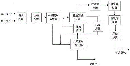
[0051] The mixed purified dry gas after desulfurization catalytic dry gas and low-separation gas enters the first-stage membrane separation device at ~2.0MPa.

[0052] One-stage membrane separation device: After hydrogen passes through the membrane, permeate gas (hydrogen-containing gas) is formed, and the hydrogen-containing gas e...

Embodiment 3

[0058] Raw gas composition

[0059] catalytic dry gas

[0060] composition

H 2

CH 4

C 2 h 6

C 2 h 4

C 3 h 8

C 3 h 6

iC 4

CO 2

O 2

h 2 S

C 5

N 2

V%

26.27

28.33

14.39

14.56

0.18

0.67

0.16

1.42

0.37

≤20ppm

0.04

13.61

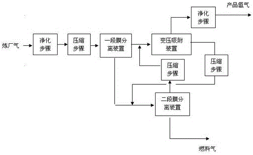
[0061] The raw material gas passes through the gas-liquid separator to remove liquid substances under the pressure of ~2.0MPa, and then enters a membrane separation device.

[0062] One-stage membrane separation device: After hydrogen passes through the membrane, permeate gas (hydrogen-containing gas) is formed, and the hydrogen-containing gas enters the pressure swing adsorption system for pressure swing adsorption hydrogen separation. The gas that fails to pass through the membrane forms the retentate gas and directly enters the second-stage membrane separation system.

[0063] The permeate gas after a stage of membrane ...


PUM


Abstract

The invention belongs to the field of chemical industry and relates to a hydrogen extraction technology in the field of chemical industry, particularly a method for improving the hydrogen recovery rate by combining a refinery gas pressure swing adsorption method and a membrane separation method. The method comprises the following steps: carrying out first-section membrane separation; carrying out pressure swing adsorption; carrying out second-section membrane separation; returning osmotic gas in membrane separation devices in the two sections to a pressure swing adsorption device; and discharging osmotic residual gas as fuel gas. The technology provided by the invention has the advantages that by combining the technical characteristics of pressure swing adsorption and membrane separation, the advantages of the individual single technology are fully exerted, and moreover, the purity and recovery rate of hydrogen are improved, and the energy consumption is reduced.

Description

technical field [0001] The invention belongs to the field of chemical industry, and relates to a hydrogen extraction technology in the field of chemical industry, in particular to a method for improving the hydrogen recovery rate by combining a refinery gas pressure swing adsorption method and a membrane separation method. Background technique [0002] Refinery gas is an important resource in petrochemical industry. Although light hydrocarbons and hydrogen in refinery gas have high utilization value, they are usually sent to the gas pipeline network as fuel gas, and some are even put into the flare to burn . The hydrogen contained in refinery gas can be separated and reused, which is more valuable than using it directly as fuel. [0003] The technologies for recovering hydrogen from refinery gas mainly include pressure swing adsorption, membrane separation and cryogenic separation. [0004] The pressure swing adsorption method is to use the characteristics that the adsorpt...

Claims


Application Information

Patent Timeline
Patent Type & Authority Applications(China)
IPC IPC(8): C01B3/56
Inventor 张汇霞陶宇鹏张剑锋杨云管英富
Owner SOUTHWEST RES & DESIGN INST OF CHEM IND
Why Eureka
Try Eureka