Cathode protection device and protection method thereof

A cathodic protection and anode technology, which is applied in the field of cathodic protection devices, cathodic protection devices and their protection, and can solve the problems that the normal design effect of the cathodic protection potentiostat cannot be exerted, it is difficult to determine the resistance, and the pipeline is burned.

Inactive Publication Date: 2015-10-21
CHINA UNIV OF PETROLEUM (BEIJING)
View PDF4 Cites 3 Cited by
  • Summary
  • Abstract
  • Description
  • Claims
  • Application Information

AI Technical Summary

Problems solved by technology

On March 10, 2012, even if the power supply of the cathodic protection potentiostat for the natural gas pipeline was disconnected from the cathode and anode wiring, it even caused a fire accident in the cabinet
However, due to the large resistance connected in series, the power consumption of the cathodic protection potentiostat is increased, and the design effect of the cathodic protection potentiostat cannot be brought into play.
More importantly, for a specific installation of a cathodic protection potentiostat, it is difficult to determine how much resistance is appropriate in series
If an excessively large resistance is connected in serie

Method used


Image

  • Cathode protection device and protection method thereof
  • Cathode protection device and protection method thereof
  • Cathode protection device and protection method thereof

Examples


Embodiment 1

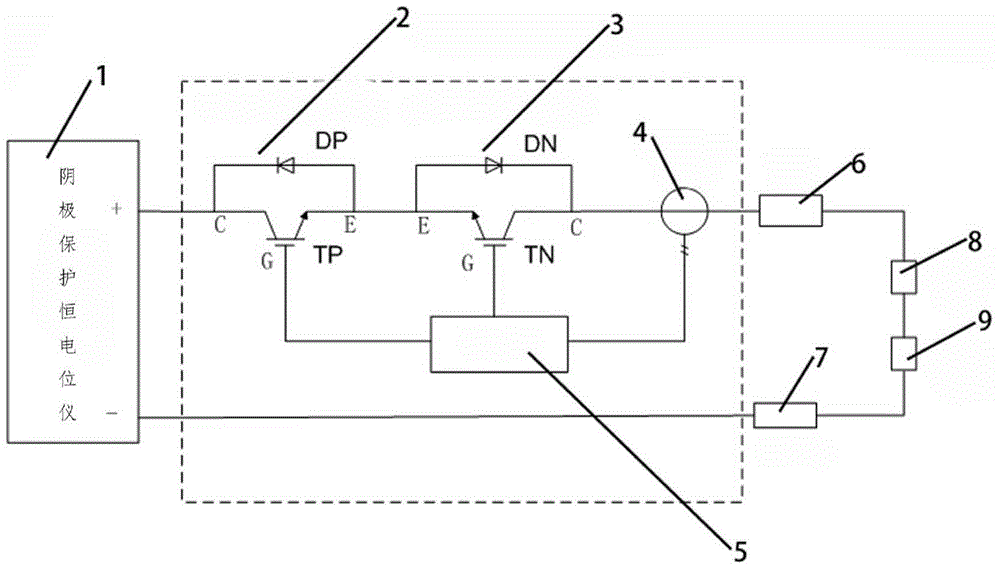
[0040] Such as figure 1 , 3 As shown in -7, a cathodic protection device includes a cathodic protection potentiostat 1, a positive power electronic switch group 2, a negative power electronic switch group 3, a current transformer 4, a computer controller 5, an anode 6, and a pipeline 7 , Soil resistance 8, coating resistance 9. The positive terminal of the cathodic protection potentiostat 1 is connected to the collector C terminal of the positive power electronic switch group 2; the emitter E terminal of the forward power electronic switch group 2 is connected to the emitter E terminal of the negative power electronic switch group 3; The collector C end of the negative power electronic switch group 3 is connected to one end of the anode 6 through the coil of the current transformer 4; the other end of the anode 6 is connected to one end of the soil resistance 8; the other end of the soil resistance 8 is connected to the coating resistance 9; the other end of the coating res...

Embodiment 2

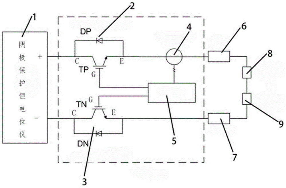
[0059] In this example, if Figure 2-7 As shown, the difference from the embodiment is that the positive end of the cathodic protection potentiostat 1 is connected to the collector C terminal of the forward power electronic switch group 2; the emitter E terminal of the forward power electronic switch group 2 passes through the current The coil of transformer 4 is connected to one end of anode 6; the other end of anode 6 is connected to one end of soil resistance 8; the other end of soil resistance 8 is connected to one end of coating resistance 9; the other end of coating resistance 9 is connected to pipeline 7 The other end of the pipeline 7 is connected to the collector C terminal of the negative power electronic switch group 3; the emitter E terminal of the negative power electronic switch group 3 is connected to the negative terminal of the cathode potentiostat 1; the positive power The gate G terminal of the electronic switch group 2 is connected to one end of the compute...


PUM


Abstract

The invention relates to a cathode protection device and a protection method thereof. The cathode protection device comprises a cathode protection constant potential rectifier, a positive power electronic switch set, a negative power electronic switch set, a current transformer and a computer controller, wherein the positive power electronic switch set, the negative power electronic switch set, the current transformer and the computer controller are serious into a protected electric appliance loop; and the computer controller receives sampling information coming from the current transformer, judges the working mode of the cathode protection constant potential rectifier, further controls opening and closing of the positive power electronic switch set and the negative power electronic switch set, transmits a failure reset command to a latch in a timing mode according to the preset time, and clears up a second-stage failure latch signal. The problem that grounding apparatus, like the cathode protection constant potential rectifier, which are connected into a pipe are possibly burnt under the conditions of geomagnetic storms, direct current transmission systems, nuclear electromagnetic pulses and the like is solved.

Description

technical field [0001] The invention relates to the technical field of electrical protection, in particular to cathodic protection devices for power transmission systems and buried oil and gas pipelines. Specifically, it relates to a cathodic protection device and a protection method thereof. Background technique [0002] The DC transmission system in which the geomagnetic storm changes from bipolar operation to unipolar operation causes excessive geomagnetically induced current (Geo-magnetically Induced Current, GIC) in buried oil and gas pipelines, and grounding equipment such as cathodic protection potentiostats It flows to the earth and causes great harm to the grounding equipment connected to the pipeline, such as the cathodic protection potentiostat installed on the pipeline, thus endangering the normal and safe operation of the pipeline. At the same time, the excessively high pipe-to-ground potential makes the cathodic protection fail, causing pipeline corrosion or h...

Claims


Application Information

Patent Timeline
IPC IPC(8): C23F13/02C23F13/06C23F13/22
Inventor 梁志珊夏鹏程生龙张举丘
Owner CHINA UNIV OF PETROLEUM (BEIJING)
Why Eureka
Try Eureka