Printing drying heat pump

A printing drying and heat pump technology, applied in printing, drying, dryer and other directions, can solve the problems of reducing the efficiency of air supply and heat recovery, reducing the effect of air supply and heat recovery, and complicated layout of air ducts, so as to improve the efficiency of air supply and heat recovery. The effect of air supply and heat recovery efficiency, reducing wind resistance energy consumption, and simple layout

Active Publication Date: 2015-10-21
GUANGDONG PHNIX ECO ENERGY SOLUTION
View PDF5 Cites 3 Cited by
  • Summary
  • Abstract
  • Description
  • Claims
  • Application Information

AI Technical Summary

Problems solved by technology

[0008] (1) The layout of the internal air duct is complex, resulting in large wind resistance, which reduces the efficiency of air supply and heat recovery
[0009] (2) The first air inlet channel 2, the second air inlet channel 4, the first return air channel 9, the second return air channel 10 and the outlet air channel 12 are all semi-closed air channels, which need to be shielded from the periphery of the unit. Only when the boards are connected can a closed air duct be formed. When the external baffles are not tightly closed, air leakage is prone to occur, thereby reducing the effect of air supply and heat recovery

Method used


Image

  • Printing drying heat pump
  • Printing drying heat pump
  • Printing drying heat pump

Examples


Embodiment Construction

[0037] The present invention will be described in detail below in conjunction with the accompanying drawings and specific implementation methods. The schematic implementation and description of the present invention are used to explain the present invention, but are not intended to limit the present invention.

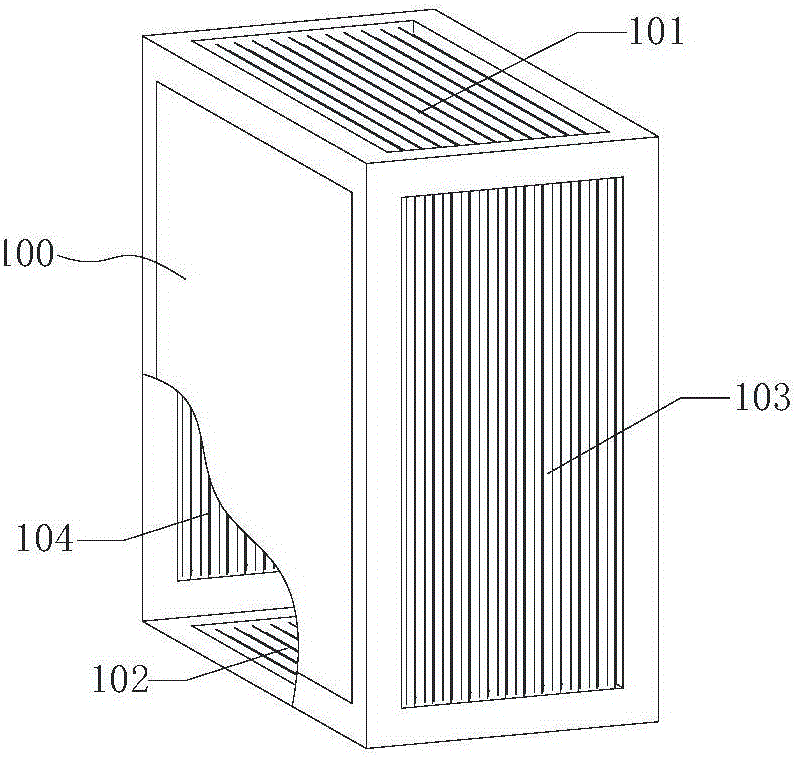
[0038] Such as image 3 As shown, it is a specific embodiment of the sensible heat exchanger 100 in the printing and drying heat pump of the present invention. The sensible heat exchanger 100 includes a fresh air inlet surface 101, and a The fresh air outlet surface 102 , the return air inlet surface 103 , and the return air outlet surface 104 facing the return air inlet surface 103 . in, image 3 In order to clearly show the fresh air outlet surface 102 and the return air outlet surface 104, it is pretended to be a partial section. In the figure, the sensible heat exchanger 100 is in the shape of a cuboid.

[0039] Such as Figure 4 Shown is a specific embodiment ...


PUM


Abstract

Disclosed in the invention is a printing drying heat pump comprising a drying machine set including a sensible heat exchanger, condenser, and an evaporator. The sensible heat exchanger contains a new air inlet surface, a new air outlet surface, a return air inlet surface, and a return air outlet surface, wherein the new air outlet surface and the return air inlet surface face the new air inlet surface and the return air outlet surface faces the return air inlet surface directly. The new air inlet surface faces an inlet of a drying machine set; and the return air inlet surface faces an air return opening of the drying machine set. The condenser is provided with a condensation windward surface facing the new air outlet surface; and areas of the condensation windward surface and the new air outlet surface are equal. The evaporator is provided with an evaporation windward surface facing the return air outlet surface; and areas of the evaporation windward surface and the return air outlet surface are equal. According to the printing drying heat pump, the ducts are distributed simply; the blowing-in resistance and the return air resistance are low; and the blowing-in and heat recovery efficiencies are high.

Description

technical field [0001] The invention relates to the technical field of printing and drying devices, in particular to a printing and drying heat pump with small air resistance and high air supply and heat recovery efficiency. Background technique [0002] Due to its high efficiency, energy saving, flexible control, and environmental protection, the printing drying heat pump is widely used in printing drying, product surface spray drying, electronic components, thermosetting adhesives, thermosetting inks, inkjet printing, printing, and clothing printing, printing and dyeing , food and other drying. [0003] At present, the printing drying heat pump is mainly composed of a drying unit, which is connected to the drying chamber. Its working principle is: the fresh air is heated by the drying unit and enters the drying chamber to dry the printed items. The heat in the hot and humid air is recovered to the drying unit, and the heat is exchanged with the fresh air, and so on, so as...

Claims


Application Information

Patent Timeline
Patent Type & Authority Applications(China)
IPC IPC(8): F26B21/04B41F23/04
CPCB41F23/04Y02P70/10
Inventor 蒋灵华向光富高翔刘远辉易毅
Owner GUANGDONG PHNIX ECO ENERGY SOLUTION
Why Eureka
Try Eureka