Grinding wheel external circle run-out detection method based on laser displacement sensor

A technology of laser displacement and detection method, which is applied in the field of mechanical precision machining, can solve the problems of multi-noise, unsuitable for frequency band filter processing, and cannot be used as a characterization parameter of the outer circle of the grinding wheel, so as to avoid human error, simple structure, and convenient operation. Effect

Active Publication Date: 2015-10-21
ZHENGZHOU RES INST FOR ABRASIVES & GRINDING CO LTD
View PDF11 Cites 32 Cited by
  • Summary
  • Abstract
  • Description
  • Claims
  • Application Information

AI Technical Summary

Problems solved by technology

However, the existing public information shows that the surface topography parameters of the grinding wheel obtained by the laser displacement sensor, such as the arithmetic mean height, root mean square deviation, maximum peak value, maximum valley value, root mean square slope area ratio, structural shape ratio, skewness, Kurtosis, peak density, etc., cannot be used as the characterization parameters of the outer circle runout of the grinding wheel, and are affected by complex detection conditions such as high speed, coarse abrasive grains, etc., and the detection object. The data measured by the laser displacement sensor contains more noise points, and It is not suitable for frequency band filtering processing, therefore, the use of laser displacement sensors to detect the outer circle runout of the grinding wheel requires special data processing of the sensor measurement data
At present, there is no scientific, universal and efficient detection method for the outer circle runout of grinding wheels in the industry

Method used


Image

  • Grinding wheel external circle run-out detection method based on laser displacement sensor
  • Grinding wheel external circle run-out detection method based on laser displacement sensor
  • Grinding wheel external circle run-out detection method based on laser displacement sensor

Examples


Embodiment Construction

[0042] The specific implementation method of the present invention will be described in detail below in conjunction with the accompanying drawings and examples, but the following examples are only used to illustrate the present invention rather than limit the scope of the present invention.

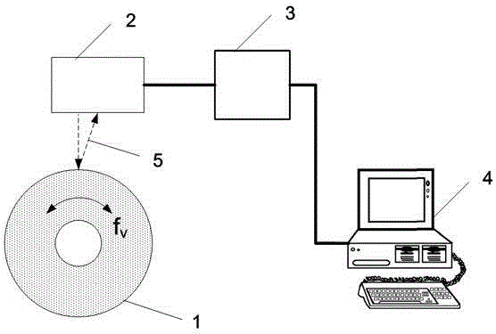
[0043] Such as figure 1 As shown, during the measurement, the tested grinding wheel 1 rotates at a certain safe speed; the laser displacement sensor 2 is installed directly in front of the outer surface of the tested grinding wheel 1, and the laser emission line 5 of the laser displacement sensor is perpendicular to the surface of the tested grinding wheel 1, The irradiation path of the laser spot passes through the center of the grinding wheel shaft; by connecting the data cable laser displacement sensor 2 to the controller 3, and the controller 3 to the computer 4, the data measured by the laser displacement sensor 2 can be transmitted to the computer 4; through software programming , ...


PUM


Abstract

The invention relates to a grinding wheel external circle run-out detection method based on a laser displacement sensor. The grinding wheel external circle run-out detection method comprises the detecting step of: firstly, installing the laser displacement sensor in front of the external circle surface of a detected grinding wheel, and connecting circuits of detection equipment; determining a signal sampling frequency and a sampling length of each measurement of the laser displacement sensor according to measurement conditions of the detected grinding wheel; setting the signal sampling frequency fk and the sampling length Ls of the laser displacement sensor through computer software; inputting the signal sampling frequency fk and the sampling length Ls into a controller of the laser displacement sensor; and detecting the external circle surface of the detected grinding wheel by using the laser displacement sensor during the rotation of the detected grinding wheel, sampling data and transmitting the data to a computer, and processing and analyzing the sampled data to obtain an external circle run-out value of the detected grinding wheel finally. The grinding wheel external circle run-out detection method based on the laser displacement sensor achieves the real-time and precise measurement of radial run-out of the external circle of the grinding wheel.

Description

technical field [0001] The invention belongs to the technical field of mechanical precision machining, and relates to a method for measuring the runout of the outer circle of a non-contact grinding wheel, in particular to a method for detecting the runout of the outer circle of the grinding wheel based on a laser displacement sensor. Background technique [0002] The grinding wheel is a circular bonded abrasive tool with a through hole in the center made of abrasives and bonds. It rotates at high speed during use. etc. for grinding. Grinding is the main processing method of precision machining. In recent years, with the development of high-speed grinding and ultra-precision grinding technology, higher requirements have been put forward for grinding wheels and their applications. In order to ensure the grinding precision and quality of the grinding wheel, it is necessary to precisely measure and control the external dimension parameters of the grinding wheel, especially the ...

Claims


Application Information

Patent Timeline
Patent Type & Authority Applications(China)
IPC IPC(8): G01B11/00G01B11/24
Inventor 冯克明师超钰朱建辉
Owner ZHENGZHOU RES INST FOR ABRASIVES & GRINDING CO LTD
Why Eureka
Try Eureka