
Boiler coal economizer emptying device

An emptying device, economizer technology, applied in the direction of feed water heater, preheating, steam generation, etc., can solve the problems of increased operating intensity of operators, longer unit start-up time, waste of boiler water, etc., to achieve shortened water supply time, reduce noise emission, and save power consumption

Active Publication Date: 2015-10-28
北京京桥热电有限责任公司
View PDF5 Cites 1 Cited by
  • Summary
  • Abstract
  • Description
  • Claims
  • Application Information

AI Technical Summary

Problems solved by technology

Even in the gas-steam combined cycle power generation unit with a high level of automation, the automatic start-stop control system (APS) of the unit has basically realized the automatic control of all processes from the auxiliary system to the completion of the "two-to-one" combination of steam, but the coal-saving The automatic emptying of the device still needs human confirmation
[0004] Manually exhaust the air from the economizer, which takes a long time (generally lasts about one hour)
However, the waste heat boiler used in the gas-steam combined cycle power generation unit has multiple economizers. During the start-up process of the unit, the operating personnel need a lot of preparation work. If multiple people are arranged to confirm the emptying of the economizer, other tasks will not be effective. It will lengthen the start-up time of the unit, and will also cause a waste of personnel; if one person is arranged to confirm the emptying of the economizer, the operation intensity of the operator will be increased, and if multiple economizers are full of water at the same time, the boiler water will be exhausted. a lot of waste

Method used

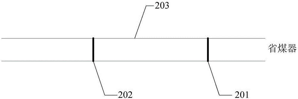
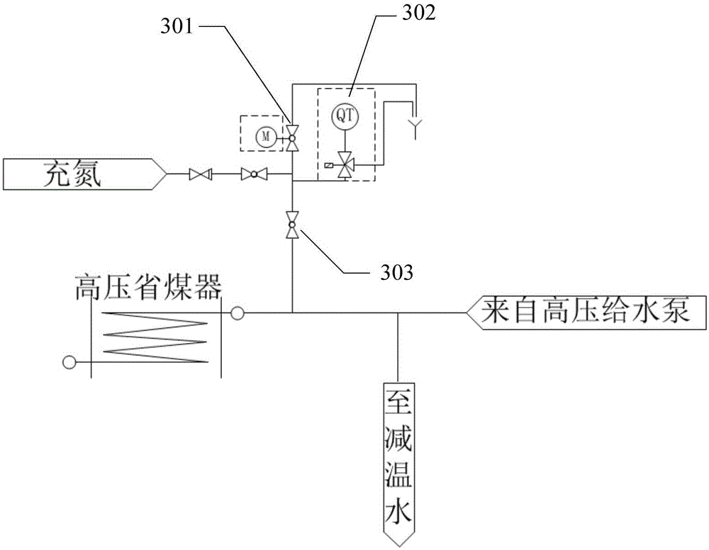

Image

  • Boiler coal economizer emptying device
  • Boiler coal economizer emptying device
  • Boiler coal economizer emptying device

Examples


Embodiment Construction

[0018] The following will clearly and completely describe the technical solutions in the embodiments of the present invention with reference to the accompanying drawings in the embodiments of the present invention. Obviously, the described embodiments are only some, not all, embodiments of the present invention. Based on the embodiments of the present invention, all other embodiments obtained by persons of ordinary skill in the art without making creative efforts belong to the protection scope of the present invention.

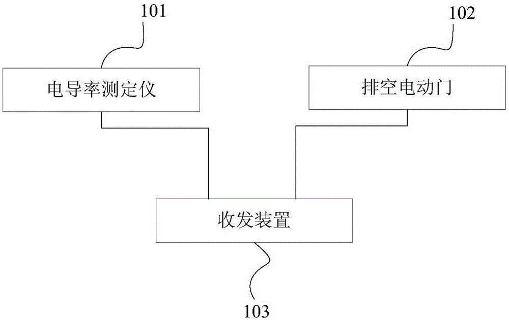
[0019] The invention provides a boiler economizer emptying device, such as figure 1 As shown, it is a schematic diagram of a boiler economizer emptying device provided by the present invention. The boiler economizer emptying device in the embodiment of the present invention includes: an emptying pipe connected to the economizer, and also includes:

[0020] Conductivity measuring instrument 101, electric valve 102 and transceiver device 103, electric valve 102,...


PUM


Abstract

The invention provides a boiler coal economizer emptying device, which comprises an emptying pipe connected with the coal economizer, a conductivity tester, an electric valve and a receiving and transmitting device, wherein the electric valve and the conductivity tester are both arranged in the emptying pipe; the conductivity tester is located between the electric valve and the coal economizer; the conductivity tester, the electric valve and the receiving and transmitting device are connected; the conductivity tester tests boiler water conductivity in the emptying pipe; the receiving and transmitting device transmits the boiler water conductivity to external equipment and receives a control instruction by the external equipment according to the boiler water conductivity; and the electric valve is closed and opened according to the control instruction. Automatic air emptying can be realized for the coal economizer, error operation probability is reduced, the unit is safer and more reliable, the water supply time is shortened, consumed power for large rotating machines such as a water pump can be saved, noise emission of the rotating machines can be reduced, and the operation intensity of an operator can be reduced.

Description

technical field [0001] The invention relates to automatic control technology, in particular to a boiler economizer emptying device. Background technique [0002] The boiler economizer is a heat exchange device that uses the heat of the flue gas at the tail of the boiler to heat the boiler feed water. The economizer is generally composed of multiple groups of serpentine tube bundles arranged side by side and inlet and outlet headers. Due to its structural limitations, the U-shaped elbow is easy to form air plugs during the water supply process of the economizer. After the boiler heats up, the air plugs will heat up rapidly, causing vaporization inside the economizer pipes, resulting in Fouling and even economizer pipe burst, boiler water circulation is blocked, and water supply to the boiler cannot be provided. Therefore, it is required that the boiler economizer must be drained of air when it is filled with water. [0003] In the actual production process of the prior art,...

Claims


Application Information

Patent Timeline
Patent Type & Authority Applications(China)
IPC IPC(8): F22D1/12
Inventor 安振源陈森森石磊王六虎马万军
Owner 北京京桥热电有限责任公司
Learn More