Current and potential transformer polarity test device

A current, voltage, and polarity testing technology, applied in measuring devices, instruments, measuring electricity, etc., can solve the problems of delay in power transmission time of substations, error-prone, complicated operation, etc., to ensure test accuracy, save power transmission time, The effect of convenience for staff

Inactive Publication Date: 2015-10-28
JINCHENG POWER SUPPLY COMPANY OF STATE GRID SHANXI ELECTRIC POWER +1
View PDF7 Cites 5 Cited by
  • Summary
  • Abstract
  • Description
  • Claims
  • Application Information

AI Technical Summary

Problems solved by technology

[0002] Potential transformer (PT) and current transformer (CT) are important electrical equipment in the power system. They are responsible for the isolation between high and low voltage systems and the conversion of high voltage to low voltage. They are installed, accepted and technically upgraded in substations. During work, the checking of the polarity of the transformer is an essential part of the relay protection staff. The wrong connection of the polarity can cause the measurement and metering device to fail to read the data correctly, and it can also cause the protection to refuse to operate or malfunction. Therefore, Transformer polarity test is of great significance to power system
[0003] There are two commonly used methods for testing the polarity of transformers. The first is to use a comprehensive transformer tester. The main function of this instrument is to use CT ratio test and output large current. The large coil inside the instrument leads to a large overall volume of the instrument. , heavy weight, in addition to complex wiring, cumbersome operation, poor anti-interference ability, error-prone, etc., even in the face of some special working environments, it cannot be used normally. If the polarity of the transformer is simply tested, these problems will be solved to a certain extent. It affects the work efficiency of relay protection workers and delays the power transmission time of the substation; the second method is to use the characteristic that the primary current of the transformer flows in from the polarity end and the secondary current flows out from the polarity end, and the pointer multimeter red , Connect the black test lead line into the secondary circuit of the transformer, set the multimeter to the DC voltage level, and then connect the negative pole of a dry battery to the primary non-polar terminal terminal of the transformer, and then use the positive pole of the dry battery to "point" The terminal of the primary polarity terminal of the transformer. At this time, the primary flow of the transformer flows into the forward current from the polarity terminal to the non-polarity terminal. Observe the pointer offset direction of the pointer multimeter. If the pointer deviates from 0 to the right, the multimeter’s The red test lead is connected to the secondary polarity end of the transformer, and the black test lead is connected to the secondary non-polar end of the transformer. This wiring is called "positive polarity". If the pointer deviates from 0 to the left, the multimeter The red test lead is connected to the secondary non-polar end of the transformer, and the black test lead is connected to the secondary polar end of the transformer. This wiring is called "negative polarity". This method requires 2-3 people to connect at the same time. Coordination, the degree of cooperation with testers is high. In the prior art, when testing the polarity of the transformer, there are problems such as time-consuming, laborious, poor anti-interference ability, difficult to operate, and cannot be used in the dark conditions of the test site.

Method used


Image

  • Current and potential transformer polarity test device

Examples


Embodiment Construction

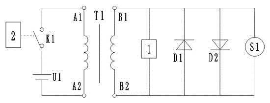
[0012] Such as figure 1 As shown, the current and voltage transformer polarity test device includes: a power supply U1, a switch K1, a light-emitting diode D1, a light-emitting diode D2, and a current direction sensing module 1 with a display screen. The positive electrode of the power supply U1 is connected in series with the switch K1. It is connected to the primary side connection terminal A1 of the current and voltage transformer T1, the negative pole of the power supply U1 is connected to the primary side connection terminal A2 of the current and voltage transformer T1, and the light emitting diode D1, the light emitting diode D2 and the current direction sensing module 1 are respectively And connected between the secondary side terminal B1 and the secondary side terminal B2 of the current and voltage transformer T1, when the current direction sensing module 1 is testing, the sensed test results can be displayed on the liquid crystal display, and the display is normal. It...


PUM


Abstract

The invention provides a current and potential transformer polarity test device, belongs to the technical field of transformer polarity test, and solves the technical problems that the invention provides the current and potential transformer polarity test device which is high in test accuracy and high in anti-interference capability and can perform measurement under the condition of a dark test site. The adopted technical scheme is that the current and potential transformer polarity test device comprises a power supply U1, a switch K1, a light-emitting diode D1, a light-emitting diode D2 and a current direction induction module with a display screen. The positive electrode of the power supply U1 is connected in series with the switch K1 and then connected with the primary side connection terminal A1 of a current and potential transformer T1. The negative electrode of the power supply U1 is connected with the primary side connection terminal A2 of the current direction induction module with the display screen. The current and potential transformer polarity test device is suitable for the technical field of electric power systems.

Description

technical field [0001] The invention discloses a current and voltage transformer polarity testing device, which belongs to the technical field of transformer polarity testing. Background technique [0002] Potential transformer (PT) and current transformer (CT) are important electrical equipment in the power system. They are responsible for the isolation between high and low voltage systems and the conversion of high voltage to low voltage. They are installed, accepted and technically upgraded in substations. During work, the checking of the polarity of the transformer is an essential part of the relay protection staff. The wrong connection of the polarity can cause the measurement and metering device to fail to read the data correctly, and it can also cause the protection to refuse to operate or malfunction. Therefore, The transformer polarity test is of great significance to the power system. [0003] There are two commonly used methods for testing the polarity of transfo...

Claims


Application Information

Patent Timeline
Patent Type & Authority Applications(China)
IPC IPC(8): G01R31/06
Inventor 畅星智马安李江龙王建峰程刚武冬冬韩晋锋王晓青徐进孔会兰郭亮赵磊崔林然
Owner JINCHENG POWER SUPPLY COMPANY OF STATE GRID SHANXI ELECTRIC POWER
Why Eureka
Try Eureka