Transformer iron core and manufacture method thereof

A manufacturing method and transformer technology, applied in the field of transformers, can solve the problems of limited improvement, reduced winding inductance, large magnetic leakage, etc., and achieve the effect of preventing magnetic leakage phenomenon

Active Publication Date: 2015-10-28
浙江仁栋电气科技有限公司
View PDF7 Cites 3 Cited by
  • Summary
  • Abstract
  • Description
  • Claims
  • Application Information

AI Technical Summary

Problems solved by technology

[0004] In order to meet the development requirements, the current through the transformer is required to be larger and larger, and this will often cause a significant drop in the inductance of the transformer winding, so that the transformer cannot work normally, resulting in premature magnetic saturation.
Therefore, in order to prevent the premature appearance of magnetic saturation, it is necessary to improve the DC superposition characteristics of the transformer. The general measure is to open a gap in the magnetic circuit of the magnetic core. Although this method can improve the DC superposition of the transformer to a certain extent characteristics, but the degree of improvement is very limited, and this method cannot be used for transformers working with large current components
Once the air gap in the core magnetic circuit is too large, the winding inductance will decrease, the magnetic flux leakage will be large, and the energy loss will be serious.

Method used


Image

  • Transformer iron core and manufacture method thereof
  • Transformer iron core and manufacture method thereof
  • Transformer iron core and manufacture method thereof

Examples


Embodiment 1

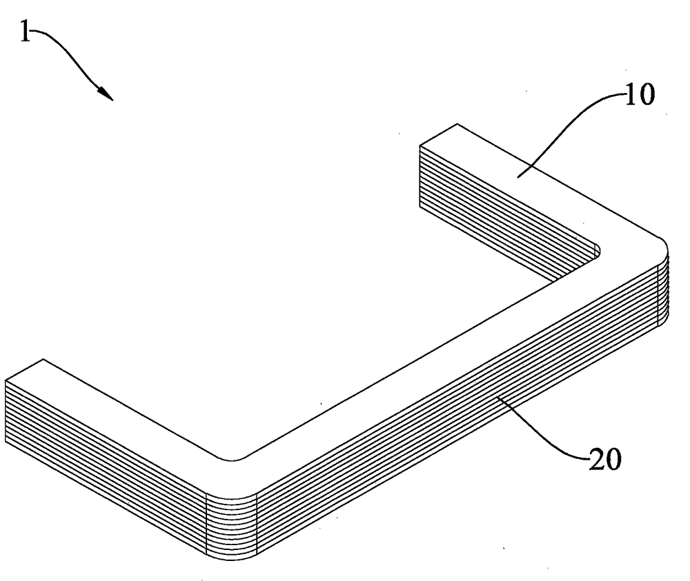
[0069] A method for manufacturing a transformer core 1, comprising the steps of:

[0070] Provide multiple sets of core laminations, each set of core laminations includes a pair of top and bottom outer core laminations 10, and a plurality of inner core laminations 20 to be processed;

[0071] grouping the inner core sheets 20, and grouping the core sheets at the same processing position into one group;

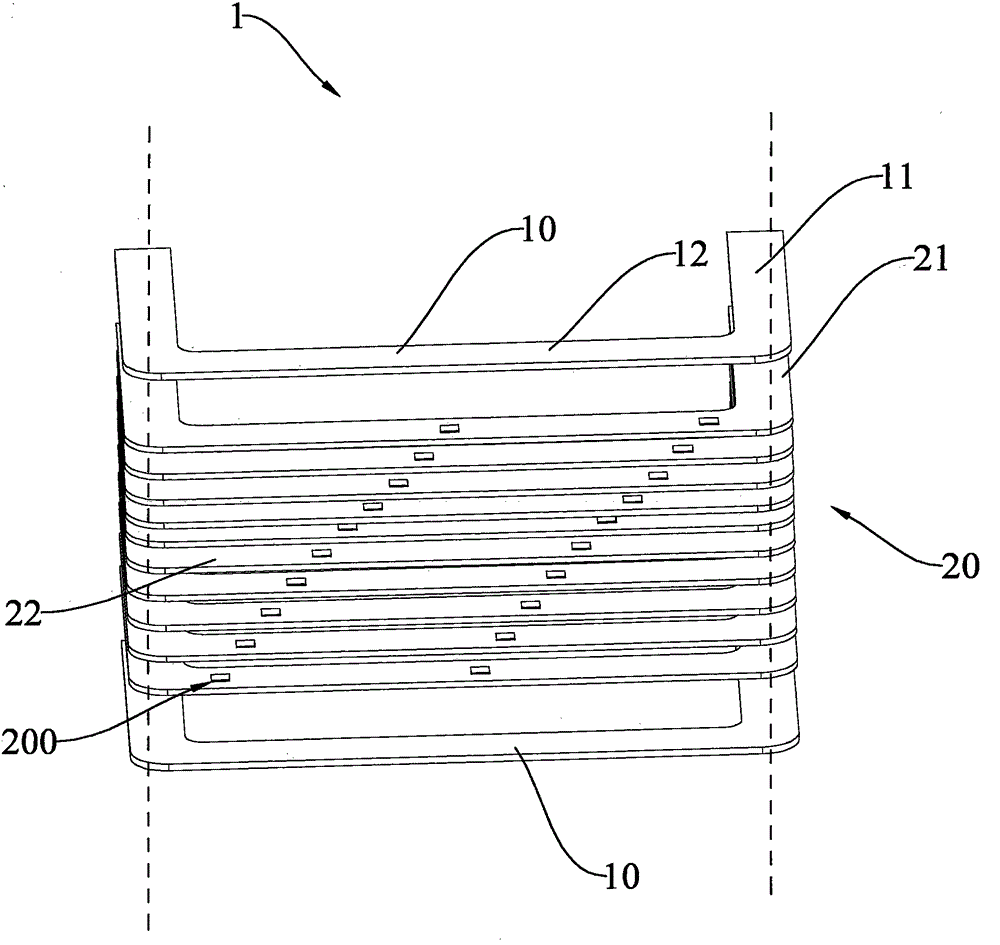
[0072] Determining the slotting preset positions of the inner core pieces 20 in each group can determine the preset positions through the punch bottom die, so as to avoid that the core slots 200 of the adjacent inner core pieces 20 are on the same longitudinal section during the slotting process Appear;

[0073] Superimpose and fix the inner iron core sheets 20 of the same group, slot the inner iron core sheets 20 of the same group by a punching machine, and form iron core slots 200 on each of the inner iron core sheets 20, if there are too many inner iron core sheets 20 in t...

Embodiment 2

[0079] providing a set of core laminations, said core laminations comprising a pair of top and bottom outer core laminations 10, and a plurality of inner core laminations 20 to be processed;

[0080] At the same time, the slotting preset position of the inner core sheet 20 is determined, and the inner core sheet 20 is punched and molded once by means of a multi-punching upper die and a multi-positioning lower die, wherein the inner core sheets 20 are placed in sequence , determine the slotting preset position of each inner core sheet 20, punch a plurality of core slots 200 in the inner core sheet 20 at one time, and obtain one silicon steel sheet with different positions of the iron core slots 200;

[0081] According to the positions of the core slots 200 of each of the inner core sheets 20, sequentially bonding and stacking each of the inner core sheets 20 to complete the lamination of the inner core sheets 20; and

[0082] The outer core sheet 10 is respectively bonded to th...

Embodiment 3

[0085]Provide multiple sets of core laminations, each set of core laminations includes a pair of top and bottom outer core laminations 10, and a plurality of inner core laminations 20 to be processed;

[0086] grouping the inner core sheets 20, and grouping the core sheets at the same processing position into one group;

[0087] Determine the slotting preset position of the iron core sheet 20 in each group, and drill a round hole at the slotting center position of each group by a drilling machine;

[0088] Cutting the inner core sheet 20 through the circular hole line for slotting of the inner core sheet 20, so that each inner core sheet 20 is provided with at least one core slot 200;

[0089] Arranging the inner core pieces 20 with the core slots 200 in partitions, placing the inner core pieces 20 at the same slotting position in the same area, and placing the inner core pieces 20 in sequence according to the slotting positions ;

[0090] Taking out a piece of inner core sh...


PUM


Abstract

The invention discloses a transformer iron core and a manufacture method thereof. The transformer iron core comprises a pair of external iron core sheets and multiple internal iron core sheets arranged between the external iron core sheets. Each internal iron core sheet is provided with at least one iron core groove for increasing magnetic resistance of the internal iron core sheet, the internal iron core sheets are stacked and connected between the external iron core sheets in a surface-to-surface manner, the iron core grooves are formed at preset positions of the internal iron core sheets, and the preset positions are adaptive to the ion core grooves of the internal iron core sheets and are in staggered arrangement for enclosing the iron core grooves of each layer.

Description

technical field [0001] The invention relates to a transformer, in particular to a transformer core for increasing magnetic saturation and effectively avoiding reduction in inductance and a manufacturing method thereof. Background technique [0002] With the rapid development of society, transformers provide reliable and uninterrupted energy for the development of the national economy. All walks of life and daily life are inseparable from electricity. A power transformer is a static electrical device that uses electromagnetic induction to convert AC power of one voltage and current into AC power of another voltage and current of the same frequency. Since there will be a certain distance between the energy production area and the power consumption area, when a certain amount of electric energy is transmitted, the higher the voltage of the transmission line, the smaller the current in the line and the corresponding line loss. In order to economically realize long-distance power...

Claims


Application Information

Patent Timeline
Patent Type & Authority Applications(China)
IPC IPC(8): H01F27/26H01F27/245H01F1/047H01F41/02
Inventor 王义明王婉儿周成升林舟波唐大忠祝华辉杨伯文陈龙
Owner 浙江仁栋电气科技有限公司
Why Eureka
Try Eureka