RFID label antenna preparation method based on liquid drop micro-injection
A technology of RFID tags and micro-spraying, applied in the direction of antenna supports/installation devices, etc., can solve the problems of high equipment requirements, high cost, complicated preparation process, etc., and achieve the effect of uniform conductivity, low cost, and simple preparation process
- Summary
- Abstract
- Description
- Claims
- Application Information
AI Technical Summary
Problems solved by technology
Method used
Image
Examples
Embodiment 1
[0033] The specific steps for preparing the RFID tag antenna 13 are as follows:
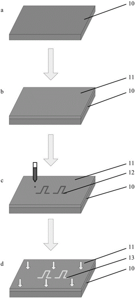
[0034] Step 1 Clean treatment of PET film substrate 10: Put the PET film in a beaker, pour an appropriate amount of concentrated sulfuric acid, heat it on a heating furnace for 10 minutes, then take it out and cool it for 10 minutes, then rinse the remaining surface of the PET film with deionized water Concentrated sulfuric acid. Wipe it dry with a cotton ball and put it into a beaker containing acetone, then place the beaker in an ultrasonic cleaner and shake for 10 minutes, take it out, rinse it with deionized water, and blow dry its surface moisture with nitrogen, such as figure 2 shown in a.
[0035] Step 2 Preparation of the hydrophobic coating 11 on the surface of the PET film substrate: first prepare a perfluoroalkyl acrylate hydrophobic solution with a concentration of 0.05w%, then put the cleaned PET film into the hydrophobic solution, and use the pulling method to remove the PET film Remo...
Embodiment 2
[0040] The specific steps for preparing the RFID tag antenna pattern 13 are as follows:
[0041] Steps 1 and 2 are the same as steps 1 and 2 described in Example 1
[0042] Step 3 Preparation of internal biconical glass micro-nozzle 6: using the internal bi-conical glass micro-nozzle preparation method to prepare internal bi-conical glass micro-nozzle with an inner diameter of 60 μm, and using the principle of capillary phenomenon The silver conductive ink is loaded into the double cone glass micro-nozzle 6 inside.
[0043] Steps 4 and 5 are the same as steps 4 and 5 described in Example 1. An RFID tag antenna with a line width of 230 μm and a resistivity of 4.2 μΩ·cm after curing can be obtained. Such as figure 2 Shown in d.
Embodiment 3
[0045] The specific steps for preparing the RFID tag antenna pattern 13 are as follows:
[0046] Steps 1, 2, 3 are the same as steps 1, 2, and 3 described in Example 2
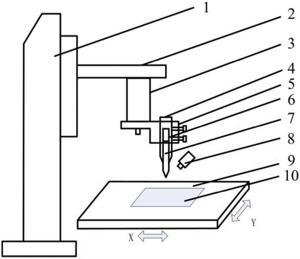
[0047] Step 4 Set the driving voltage amplitude of the piezoelectric actuator 3 to 40V, the driving frequency to 2Hz, set the motion parameters of the two-dimensional worktable 9 so that the droplet overlap rate is 40%, and the motion pattern of the worktable 9 selects the bending dipole Sub-antenna pattern. Drive the internal biconical glass micro-nozzle 6 to micro-spray the nano silver conductive ink onto the hydrophobic coating 11 to obtain the RFID tag antenna pattern 12, and the line width of the prepared RFID tag antenna pattern 12 is 130μm, such as figure 1 , 2 c is shown.
[0048] Step 5 is the same as step 5 described in Example 1. An RFID tag antenna with a line width of 134μm and a resistivity of 4.8μΩ·cm after curing can be obtained. Such as figure 2 Shown in d.
PUM
| Property | Measurement | Unit |
|---|---|---|
| Outer diameter | aaaaa | aaaaa |
| The inside diameter of | aaaaa | aaaaa |
| The inside diameter of | aaaaa | aaaaa |
Abstract
Description
Claims
Application Information
 - R&D
- Intellectual Property
- Life Sciences
- Materials
- Tech Scout
- Unparalleled Data Quality
- Higher Quality Content
- 60% Fewer Hallucinations
Browse by: Latest US Patents, China's latest patents, Technical Efficacy Thesaurus, Application Domain, Technology Topic, Popular Technical Reports.
© 2025 PatSnap. All rights reserved.Legal|Privacy policy|Modern Slavery Act Transparency Statement|Sitemap|About US| Contact US: help@patsnap.com


