Motor

A technology for electric motors and motor stators, which is applied to electric components, electrical components, electromechanical devices, etc., can solve the problems of poor stability, load shaft end runout, large coupling moment of inertia, etc., and achieve stable dynamic performance and compact axial size. , the effect of low precision requirements

Active Publication Date: 2015-10-28
NANJING UNIV OF POSTS & TELECOMM
View PDF5 Cites 0 Cited by
  • Summary
  • Abstract
  • Description
  • Claims
  • Application Information

AI Technical Summary

Problems solved by technology

[0006] Disadvantages: 1. The coupling is easily damaged in the process of power transmission, with high cost and poor stability; 2. The size of the equipment along the axis of the servo motor is larger and will occupy more space; 4. The coupling itself The moment of inertia is large. On the one hand, the acceleration is poor, which greatly restricts the processing speed of the workpiece; on the other hand, the energy consumption during the processing is high.
[0009] Disadvantages: 1. The mechanism is an over-constrained structure, and the deviation of the coaxiality (including parallelism) between the motor shaft end and the load shaft is inevitable. The deviation of the coaxiality will cause a large internal force of the mechanism, which can easily cause the load shaft, Fatigue damage of parts such as bearings, and even "stuck" of the mechanism when the over-constraint is serious; 2. The impact load at the actuator end directly acts on the motor, resulting in large vibration and impact, and vibration and noise during the operation of the machine tool are inevitable
[0012] Disadvantages: During the machining process, the deflection deformation of the load shaft under the load force is inevitable, which will cause the beating of the load shaft end, which will lead to the change of the air gap between the rotor and the stator

Method used


Image

  • Motor
  • Motor
  • Motor

Examples


Embodiment Construction

[0059] The present invention will be further described in detail below in conjunction with the accompanying drawings and specific preferred embodiments.

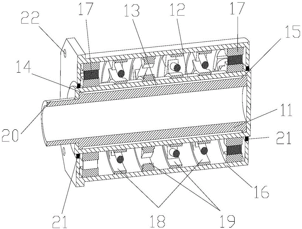
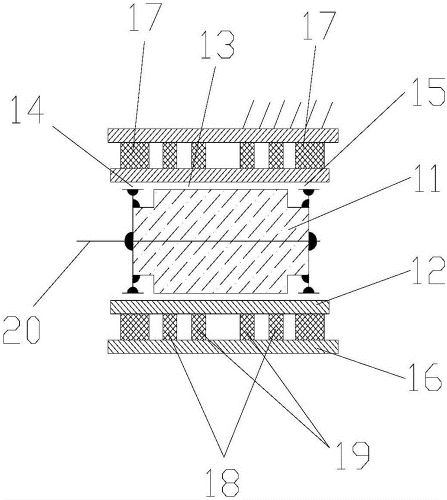
[0060] Such as figure 1 and figure 2 As shown, a motor includes a motor rotor 11 and a motor stator 12 coaxially sleeved on the outer periphery of the motor rotor 11 .

[0061] One end of the motor rotor 11 is provided with an output shaft 20 that can be rigidly and fixedly connected directly to the load shaft, and the output shaft 20 is preferably a hollow structure.

[0062] The motor rotor 11 and the motor stator 12 are articulated through the front bearing 14 and the rear bearing 15 .

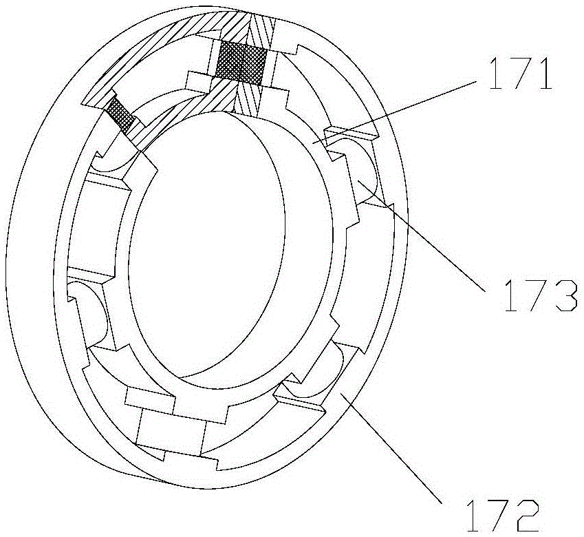
[0063] The outer periphery of the motor stator 12 is coaxially fitted with a fixed frame 16, and at least one elastic component is arranged between the motor stator 12 and the fixed frame 16, and the elastic component includes several suspension assemblies 17, several first torsion assemblies 18 and Several second torsion components 1...


PUM


Abstract

The invention discloses a motor comprising a motor rotor, a motor stator and a fixing frame. The motor rotor and the motor stator are hinged via a front bearing and a rear bearing. At least one elastic assembly is arranged between the motor stator and the fixing frame. Each elastic assembly comprises multiple suspension assemblies, and a first torsion assembly and a second torsion assembly which are symmetrically arranged between the two adjacent suspension assemblies. Each suspension assembly comprises multiple groups of first flexible elements which are arranged along a radial direction. The first torsion assembly and the second torsion assembly respectively comprise multiple groups of second flexible elements which are arranged in a clockwise or anticlockwise way. After application of the aforementioned structure, coaxiality deviation and parallelism deviation between a load shaft end and a servo motor output shaft can be absorbed without over-constraint; the axial size is compact, load inertia of the mechanism is low and high-speed processing can be realized; and the air gap between the motor rotor and the motor stator is constant without over-constraint or mechanism internal force, and the motor is suitable for high-speed and heavy-load application occasions.

Description

technical field [0001] The invention relates to a motor, in particular to a motor structure suitable for use when the deviation of coaxiality and parallelism is large. Background technique [0002] Electric motors are used in a wide range of industrial applications, almost everywhere. However, in practical applications, the deviation of the coaxiality and parallelism between the motor output shaft and the load shaft end is unavoidable, which brings many difficulties to practical applications. [0003] The motors of the prior art are mainly as follows: [0004] 1. Connect the shaft end of the load with the shaft end of the servo motor through a coupling [0005] Advantages: The coupling is an elastic component. On the one hand, it can absorb the coaxiality deviation between the load shaft and the output shaft of the motor, so that it will not cause over-constraint and cause fatigue damage to the bearing; on the other hand, the elastic element (coupling) can It plays the ro...

Claims


Application Information

Patent Timeline
IPC IPC(8): H02K7/00H02K1/18
Inventor 徐丰羽申景金蒋国平
Owner NANJING UNIV OF POSTS & TELECOMM
Why Eureka
Try Eureka