Heating Rod for Critical Heat Flux Test

A critical heat flux density and test technology, applied in the field of nuclear reactor test research, can solve the problems of inability to achieve rapid and large heat exchange, large diameter of electric heating rods, and inability to process and assemble, and achieve precise control of effective heating length, accurate size and rapidity The effect of a large amount of heat exchange

Active Publication Date: 2016-09-28
CHINA NUCLEAR POWER TECH RES INST CO LTD +2
View PDF8 Cites 3 Cited by
  • Summary
  • Abstract
  • Description
  • Claims
  • Application Information

AI Technical Summary

Problems solved by technology

[0008] U.S. Patent US4156127 also discloses an electric heating rod, which is composed of three extruded layers, the inner layer is a thin polytetrafluoroethylene tube, which plays the role of insulation and heat exchange with the medium; the middle layer is made of carbon and polytetrafluoroethylene The mixture of ethylene conducts heat and conducts heat; the outermost layer is a polytetrafluoroethylene thick tube, which acts as insulation and heat insulation from the environment; the wires connected to the middle layer are drawn out from the beginning and end of the heating rod. When a voltage is applied to the wires, it will A current flows through the middle layer of evenly arranged carbon materials, thereby generating uniform heat generation; therefore, the electric heating rod can generate heat evenly distributed along the axial direction, but the maximum temperature can only reach 260°C, which is far below the critical heat flux test. The required temperature; the heating layer and the medium are insulated and conducted through polytetrafluoroethylene, which cannot achieve rapid and large-scale heat exchange; the diameter of the electric heating rod is large, and it cannot be processed and assembled according to the size of nuclear fuel

Method used


Image

  • Heating Rod for Critical Heat Flux Test
  • Heating Rod for Critical Heat Flux Test
  • Heating Rod for Critical Heat Flux Test

Examples


Embodiment Construction

[0020] Embodiments of the present invention will now be described with reference to the drawings, in which like reference numerals represent like elements.

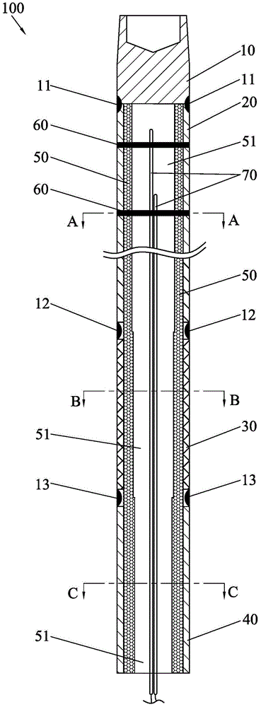
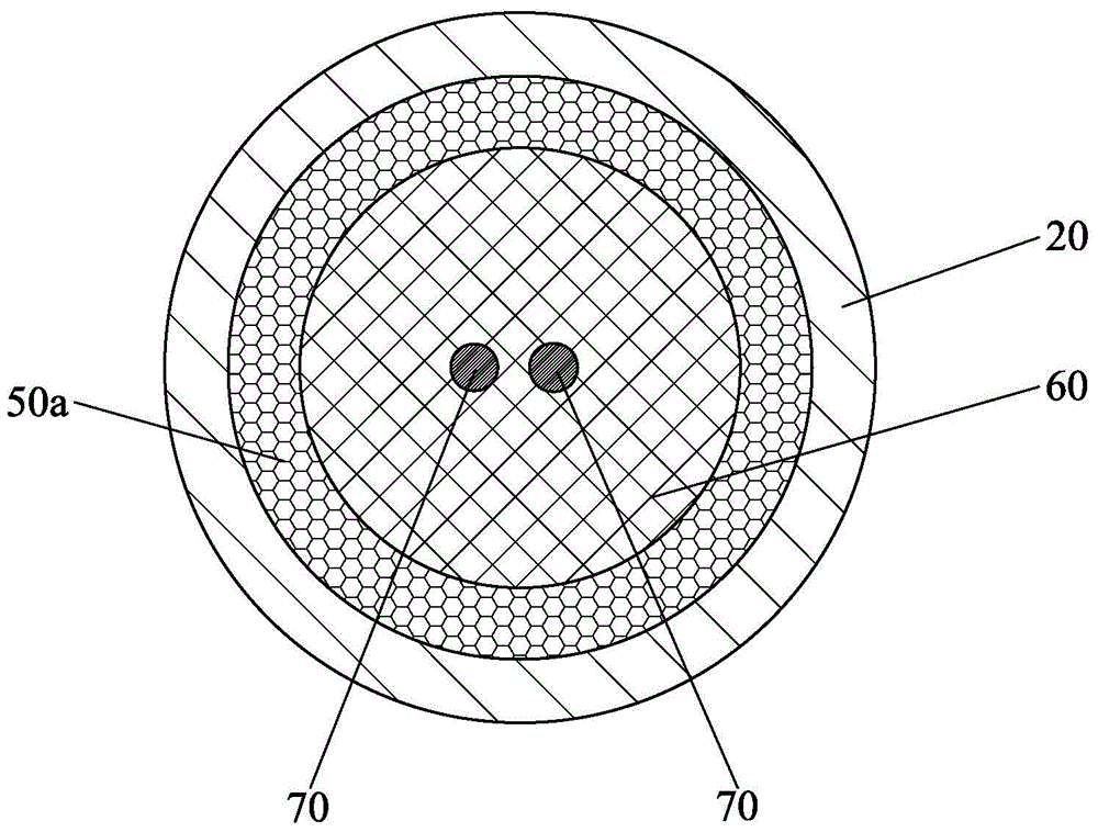
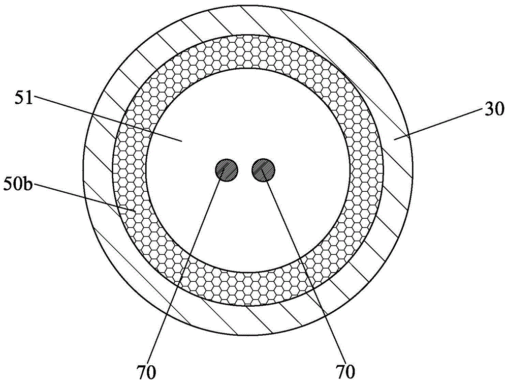
[0021] Such as figure 1 As shown, the heating rod 100 for the critical heat flux test of the present invention is used to simulate the heat release of nuclear fuel and carry out the critical heat flux test, which includes a nickel rod 10, a heating tube 20, a nickel tube 30, a copper tube 40, a ceramic part 50, Copper sheet 60 and thermocouple 70, the upper end of the nickel rod 10 is connected to the external upper live equipment, the lower end of the nickel rod 10 is docked with the upper end of the heating tube 20 and sealed and fixedly connected, and the nickel rod 10 is used for heating The pipe 20 is docked and fixed to ensure the strength while reducing the ineffective calorific value; the lower end of the heating pipe 20 is docked with the upper end of the nickel pipe 30 and sealed and fixedly connected, and the h...


PUM


Abstract

A heating rod for a critical heat flux test comprises a nickel rod, a heating pipe, a nickel pipe, a copper pipe, a ceramic member, copper pieces and a thermocouple. The heating pipe, nickel pipe and copper pipe are connected sequentially in series with sealed and fixed connections, and form a rod body having a hollow structure. The nickel rod is connected to an external upper energized device, and the copper pipe is connected to an external lower energized device. The ceramic member is attached to an inner wall of the rod body and surround the same to form a thermal cavity. The copper pieces are uniformly and horizontally disposed in the thermal cavity and located in the heating pipe. The thermocouple is suspended in the thermal cavity and is fixed by the copper pieces. The present invention provides a high heating temperature, high heat flux and compact structure to meet the requirements of a critical heat flux test, and measures and outputs a temperature parameter by the thermocouple in real-time, such that heat release of a nuclear fuel is accurately simulated, and critical heat flux testing requirements are effectively met. Furthermore, a critical heat flux of a nuclear fuel rod in different operating conditions can be measured to support research and development of a novel nuclear fuel component.

Description

technical field [0001] The invention relates to the field of nuclear reactor test research, in particular to a heating rod used for studying critical heat flux density tests of nuclear fuel assemblies. Background technique [0002] In convective boiling, there are mainly two types of critical heat flux: deviating nucleate boiling and dry out. In the steady-state thermal design of PWR nuclear power plant, usually only subcooled boiling and saturated boiling with low vapor content are encountered, so the heat flux away from nucleate boiling is particularly important. [0003] The mechanism model of deviating nucleate boiling mainly includes three types: (a) when a large steam bubble is formed on the wall of the heating element, the thin liquid film at the bottom evaporates continuously, forming dry spots, which leads to the deterioration of heat transfer on the wall of the heating element; (b) ) When the bubble layer on the wall of the heating element is thick enough to preve...

Claims


Application Information

Patent Timeline
Patent Type & Authority Patents(China)
IPC IPC(8): H05B3/44
CPCH05B3/44
Inventor 文青龙卢冬华张戈杨智翔李嘉明
Owner CHINA NUCLEAR POWER TECH RES INST CO LTD
Why Eureka
Try Eureka