
Nanofiber cluster membrane dryer

A technology of nanofibers and dryers, applied in chemical instruments and methods, separation of dispersed particles, separation methods, etc., can solve problems such as high manufacturing costs and complex structures, and achieve low cost, small volume, innovative effect and life.

Inactive Publication Date: 2015-11-04
JIANGSU XINGAOKE ANALYTICAL INSTR
View PDF1 Cites 0 Cited by
  • Summary
  • Abstract
  • Description
  • Claims
  • Application Information

AI Technical Summary

Problems solved by technology

But the disadvantage is that the structure is more complicated and the manufacturing cost is too high

Method used


Image

  • Nanofiber cluster membrane dryer

Examples


Embodiment Construction

[0010] Below in conjunction with embodiment the present invention is further described.

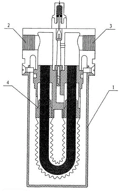
[0011] As shown in the figure, there are air inlets 2 and air outlets 3 on both sides of the cavity tube 1, and nanofiber bundles 4 are arranged in the cavity tube. The wet compressed air to be dried enters from the inlet 2 and passes through the inner hole of the nanofiber bundles. It is discharged from the air outlet 3, and the water in the gas to be measured will permeate from the inner wall to the outer wall due to the pressure difference between the inner and outer walls of the fiber bundle by using the membrane permeation principle of the polymer fiber. The nanofiber bundles 4 are twisted in the cavity, the sealing plugs at both ends are bonded by polymer glue, and the fiber bundles are made of nanopolymer materials. The gas to be dried enters from the gas, and is discharged from the gas outlet after passing through the inner hole of the nanofiber bundle. Using the membrane permeati...


PUM


Abstract

The invention discloses a nanofiber cluster membrane dryer which comprises a cavity tube, an air inlet and an air outlet. Fiber clusters are arranged in the cavity tube, the air inlet and the air outlet are formed in the side face of the cavity tube, and nanofiber clusters wound into a fried dough twist shape are arranged in the cavity tube. Sealing plugs are embedded in the two ends of the nanofiber clusters in parallel and are communicated with an air chamber connected with the air inlet and the air outlet. The dryer has the advantages that the structure is simple, the size is small, cost is low, ventilation is performed through the dozens of fiber clusters at the same time, the permeable effect is good, the dehydrating rate is high, sealing performance is good, air and water do not overflow, pollution is not caused, the effect is greatly improved, and the service life is greatly prolonged.

Description

technical field [0001] The invention relates to a gas dryer, in particular to a nanofiber bundle membrane dryer used in an analytical instrument. Background technique [0002] In the commonly used gas drying device, the color-changing silica gel is placed in a cylindrical glass tube, and the mouth of the tube is sealed with a cork. The air outlet is connected and then hung on the rear wall of the instrument as a whole. Air flows in from a low position and flows out from a high position, forming a loop. In similar devices, when replacing the color-changing silica gel, it is necessary to unplug the latex tube and remove the glass tube from the instrument to become an independent component, then uncover the cork, turn over 180°C to pour out the old color-changing silica gel, and remove it from the instrument. Lower the glass tube and pour out the old color changing silicone. After replacing the new color-changing silica gel, it was not installed in the original order. This ...

Claims


Application Information

Patent Timeline
Patent Type & Authority Applications(China)
IPC IPC(8): B01D53/22B01D53/26
Inventor 朱明俊
Owner JIANGSU XINGAOKE ANALYTICAL INSTR
Learn More