Welding fixture for nuclear fuel assembly positioning grillwork

A technology for nuclear fuel components and welding fixtures, applied in welding equipment, welding equipment, laser welding equipment, etc., can solve problems such as poor design accuracy, affecting welding quality, and cumbersome welding fixture structure, so as to improve welding quality, easy processing, prevent loose effect

Inactive Publication Date: 2015-11-04
HARBIN INST OF TECH
View PDF8 Cites 9 Cited by
  • Summary
  • Abstract
  • Description
  • Claims
  • Application Information

AI Technical Summary

Problems solved by technology

[0003] The purpose of the present invention is to provide a welding fixture used for positioning grids of nuclear fuel assemblies in order to solve the problems of conventional welding fixtures with cumbersome structure, poor design accuracy and influence on welding quality

Method used


Image

  • Welding fixture for nuclear fuel assembly positioning grillwork
  • Welding fixture for nuclear fuel assembly positioning grillwork
  • Welding fixture for nuclear fuel assembly positioning grillwork

Examples


specific Embodiment approach 1

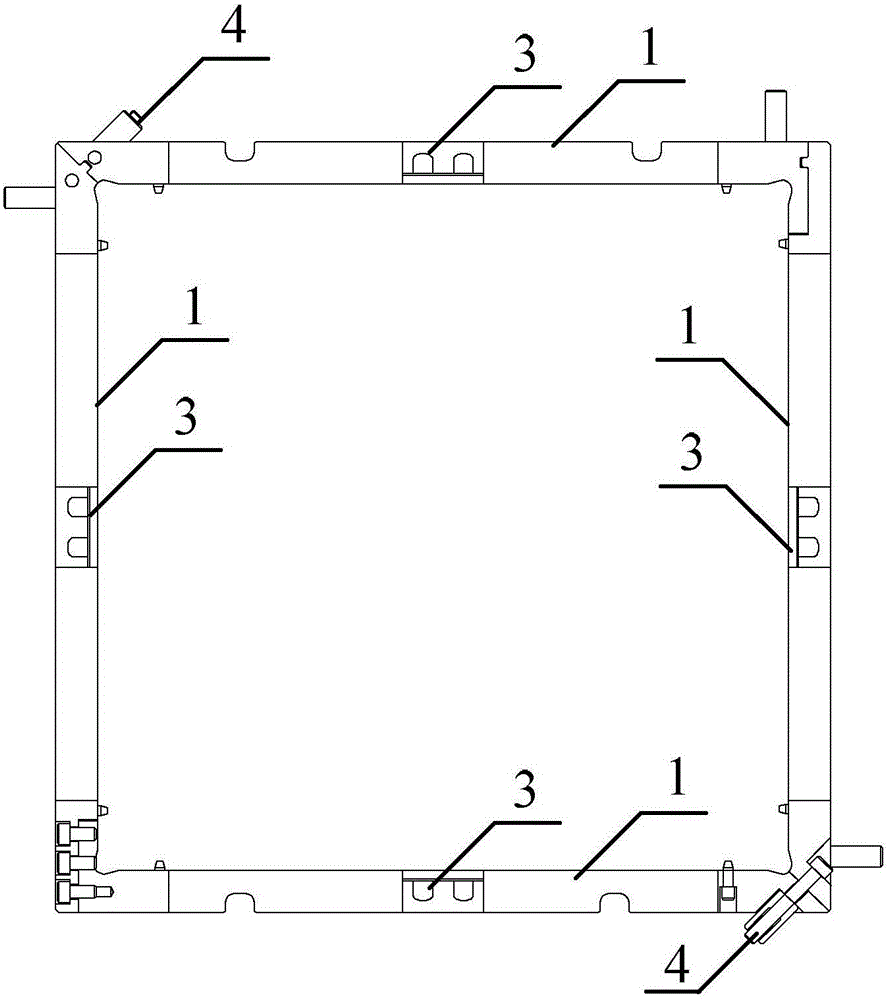
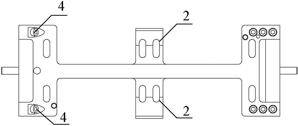
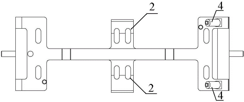
[0016] Specific implementation mode one: combine Figures 1 to 5 To illustrate this embodiment, the welding fixture used for the positioning grid of nuclear fuel assemblies described in this embodiment includes a traveling fixture and a casing fixture;

[0017] The accompanying fixture includes four positioning plates 1, and the four positioning plates 1 surround a square frame, and the length and width of the square area inside the square frame can be adjusted, and each positioning plate 1 is provided with two rows of light-through holes 2, and each positioning plate 1 is provided with a positioning pin 3;

[0018] The casing fixture includes an upper cover plate and a bottom plate, and a through hole 5 is opened on the bottom plate corresponding to the casing pipe, and a plum blossom hole 6 is opened on the upper cover plate corresponding to the casing pipe, and four holes are installed around the plum blossom hole 6. There are four protrusions distributed symmetrically.

...

specific Embodiment approach 2

[0032] Specific Embodiment 2: This embodiment is a further limitation of the welding jig for the nuclear fuel assembly positioning grid described in Embodiment 1. In this embodiment, the inner surfaces of the upper cover plate and the bottom plate are provided with inner strips Groove for point-by-point positioning over the full length.

[0033] The inner surfaces of the upper cover and the bottom plate are provided with grooves for point-by-point positioning of the vertical and horizontal inner strips. The strips in the grid are inserted into the positioning grooves of the bottom plate of the fixture for overall positioning, and the two-dimensional positioning of the grid plane is completed.

[0034] Specific implementation method three: combination figure 1 Describe this embodiment. This embodiment is a further limitation of the welding fixture used for the positioning grid of nuclear fuel assemblies described in Embodiment 1. In this embodiment, the inner surfaces of the up...

specific Embodiment approach 4

[0036] Specific implementation mode four: combination figure 1 Describe this embodiment. This embodiment is a further limitation of the welding jig used for the positioning grid of nuclear fuel assemblies described in Embodiments 1 and 2. Wire.

[0037] Observe the welding process through the CCD camera of the laser welding head. If there is a deviation between the engraved line and the coordinate track of the motion system, control the laser three-dimensional motion mechanism to align the cross mark on the CCD monitor with the starting point and end point of the engraved line on the welding fixture. The system can automatically complete the deviation correction to further improve the welding accuracy.


PUM


Abstract

The invention discloses a welding fixture for a nuclear fuel assembly positioning grillwork, and relates to the welding technology of the nuclear fuel assembly positioning grillwork. The welding fixture aims at solving the problems that a conventional welding fixture is complex in structure, the design accuracy is worse, and the welding quality is influenced. A follow fixture comprises a square frame defined by four positioning plates, and the length and the width of the square frame are adjustable; each positioning plate is provided with a positioning pin, an upper row of light through holes and a lower row of light through holes; and a sleeve fixture comprises an upper cover plate and a base plate, a through hole is formed in the position, corresponding to a sleeve, on the base plate, a plum-blossom-shaped hole is formed in the position, corresponding to the sleeve, on the upper cover plate, and four symmetrically-arranged protrusions are installed on the periphery of the plum-blossom-shaped hole. The welding fixture is simple in structure and easy to machine, and the welding requirement can be completely met; compared with a conventional welding manner and a conventional welding fixture, the welding quality can be greatly improved; and the follow fixture serves as a transition structure for assembling and welding the fixture, the conversion continuity of the two parts is guaranteed, all welding seam connection can be completed at a time, and the welding fixture is suitable for welding of the nuclear fuel assembly positioning grillwork.

Description

technical field [0001] The invention relates to the welding technology of a nuclear fuel assembly positioning grid. Background technique [0002] The nuclear fuel assembly positioning grid includes a plurality of inner strips, four outer strips and sleeves, and has a square structure as a whole. There are slender openings at equal intervals on the inner and outer strips, and the inner strips are interspersed with each other to form rows of small squares. There are many slender openings on the outer strip, and the two ends of the inner strip are inserted into the outer strip. In the opening on the top, the outer strip is fixed around the square area formed by the inner strip, and the sleeve is located in the small square formed by the inner strip. The accuracy of the welding fixture of the grid must be able to meet the welding requirements of various welds of the grid. The conventional welding method is to weld the intersection lines between the inner strips and all the int...

Claims


Application Information

Patent Timeline
Patent Type & Authority Applications(China)
IPC IPC(8): B23K37/04B23K26/70
CPCB23K37/0443B23K2101/24
Inventor 陈彦宾陶汪闫相和李纵跃林泳乔亮苏轩
Owner HARBIN INST OF TECH
Why Eureka
Try Eureka