High-precision grease removing device in water

A high-precision, water-collecting pipe technology, applied in the direction of water/sewage multi-stage treatment, water/sludge/sewage treatment, chemical instruments and methods, etc., can solve the problem of short service life of filter medium, poor impact resistance of incoming liquid, Backwashing effect is not good and other problems, to achieve the effect of enhancing separation efficiency and improving impact resistance

Inactive Publication Date: 2015-11-04
高希山
View PDF8 Cites 0 Cited by
  • Summary
  • Abstract
  • Description
  • Claims
  • Application Information

AI Technical Summary

Problems solved by technology

[0003] The current high-precision oil-water separation equipment has poor impact resistance to incoming liquid, unstable operation, short filter medium life, poor backwashing effect, and the water outlet effect cannot meet the requirements after short-term operation.
[0004] The current high-precision oil-water separator has poor recoil effect after the initial ideal treatment stage, is easy to clog, the water outlet in the later stage is seriously substandard, and cannot be completely backwashed. The actual service life of the filter medium is short, and the filter element is seriously damaged during operation. Replace the filter material. Frequent, consumes a lot of manpower and material resources, and will also consume too much clean water due to frequent backwashing in the later stage.

Method used


Image

  • High-precision grease removing device in water
  • High-precision grease removing device in water
  • High-precision grease removing device in water

Examples


Embodiment Construction

[0025] The present invention will be further described below in conjunction with accompanying drawing:

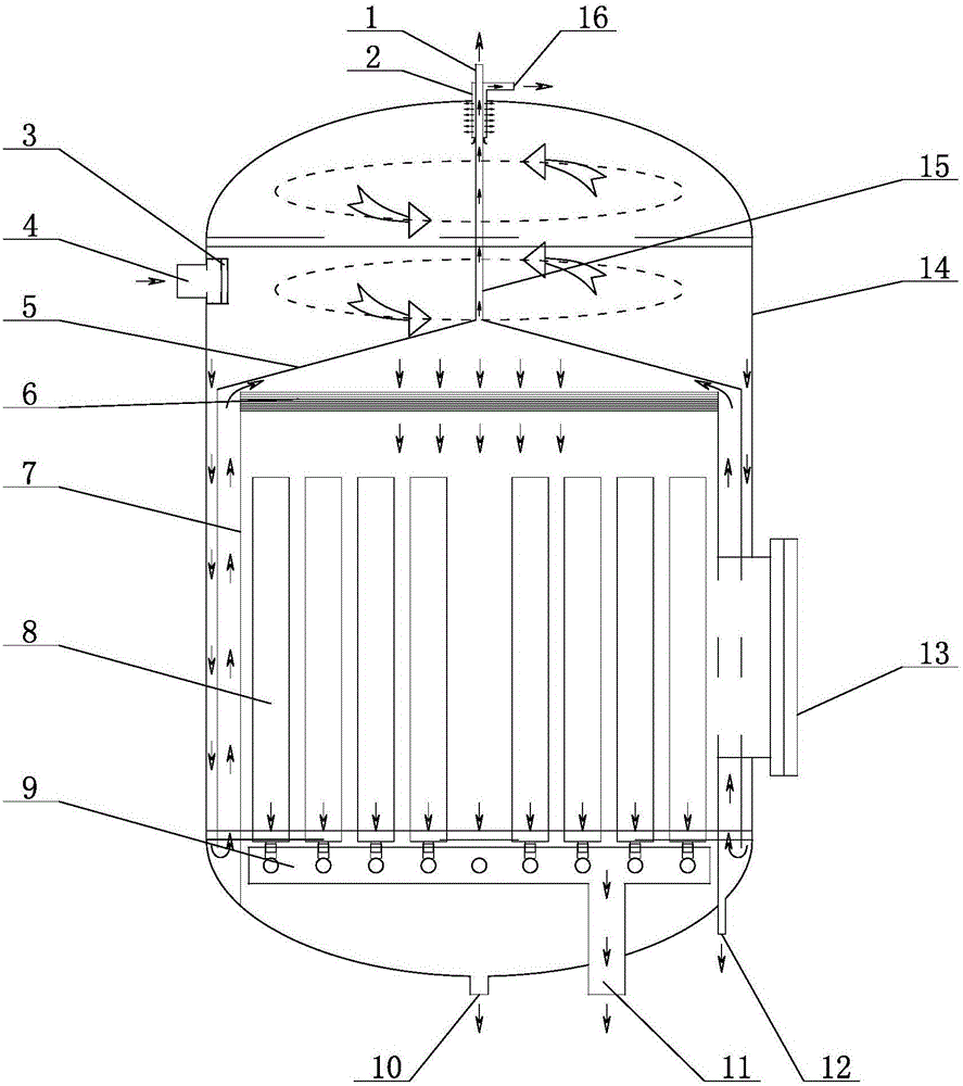
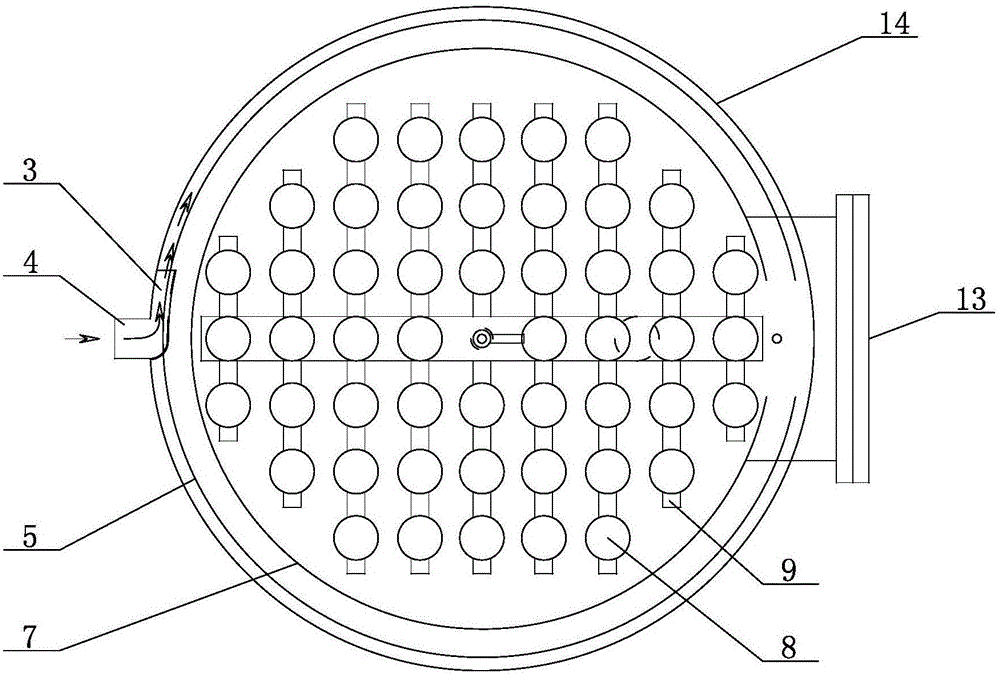
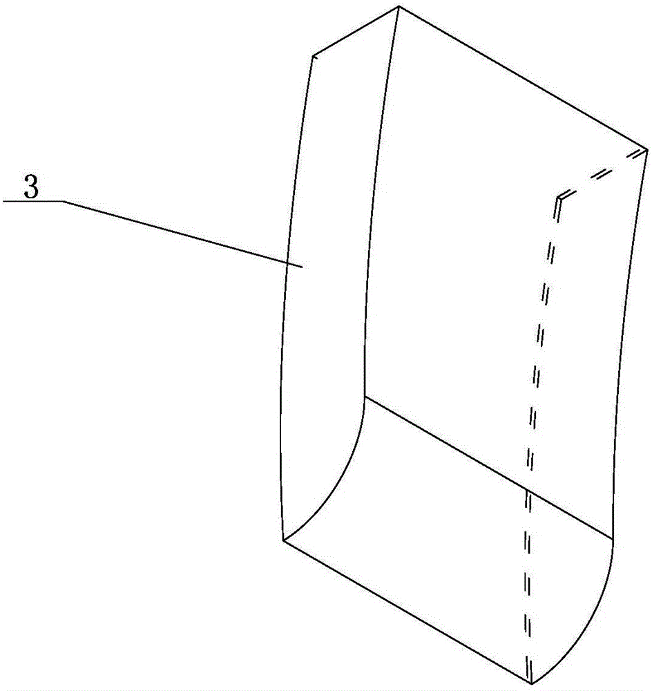
[0026] Such as Figure 1 ~ Figure 3 As shown, the high-precision water degreasing device of the present invention includes a cylinder body 14, a compartment housing 5 is arranged in the cylinder body 14, a gap is provided between the bottom of the compartment housing 5 and the bottom of the cylinder body 14, and the compartment housing 5 The upper part is a cyclone separation chamber, and the lower part is a precision separation chamber. The cyclone separation chamber includes a water inlet 4 and a first overflow port 16. The top of the sub-chamber housing 5 is connected to the second overflow port 1, and the second overflow port 1 is placed in the Outside the cylinder 14, there is a deflector 7 in the precision separation chamber, the bottom of the deflector 7 is sealed and connected with the bottom of the cylinder 14, the top of the deflector 7 is provided with a fiber se...


PUM


Abstract

The invention belongs to the field of water processing filtering devices and particularly relates to a high-precision grease removing device in water. The high-precision grease removing device in water comprises a cylinder. A compartment shell is arranged in the cylinder. A gap is formed between the bottom of the compartment shell and the bottom of the cylinder. A hydrocyclone separation room is arranged at the upper portion of the compartment shell, and a precise separation room is arranged at the lower portion of the compartment shell. The hydrocyclone separation room comprises a water inlet and a first overflow opening. A second overflow opening is connected to the top of the compartment shell and is formed in the outer portion of the cylinder. A diversion plate is arranged in the precise compartment room, and the bottom of the diversion plate is connected with the bottom of the cylinder in a sealed mode. A fiber separation film is arranged on the top of the diversion plate. A water collection pipe network is arranged at the bottom of the diversion plate and is provided with an oil water separation core communicated with the interior of the water collection pipe network. A water outlet is formed in the bottom of the water collection pipe network. The space in the cylinder is divided into two different levels of oil removing rooms, namely a precise separation room and a hydrocyclone separation room, through the compartment shell, high-concentration oil impurities are removed through separation of the hydrocyclone separation room, high-precise separation is conducted through the precise separation room, the separation capability is improved, and therefore the space of the cylinder can be fully utilized.

Description

technical field [0001] The invention relates to a high-precision water degreasing device, which belongs to the field of water treatment and filtering equipment. Background technique [0002] Existing high-precision oil-water separation technology is widely used in oily water treatment in petroleum, chemical industry, smelting, machinery or light industry and other departments. With the deep exploitation of oil, the large-scale development of chemical enterprises and the strict requirements for environmental protection, the separation technology of oily sewage has been paid more and more attention. [0003] The current high-precision oil-water separation equipment has poor impact resistance to incoming liquid, unstable operation, short filter medium life, poor backwashing effect, and the water outlet effect cannot meet the requirements after short-term operation. [0004] The current high-precision oil-water separator has poor recoil effect after the initial ideal treatment ...

Claims


Application Information

Patent Timeline
IPC IPC(8): C02F9/02
Inventor 高希山
Owner 高希山
Why Eureka
Try Eureka