Undercarriage buffer

A technology of landing gear buffers and buffers, applied in the field of aeronautical engineering, can solve the problems of complex structure of landing gear buffers and lack of small aircraft landing gear buffers, etc., and achieve the effect of simple structure, reliable performance and strong scalability

Inactive Publication Date: 2015-11-04
HARBIN
View PDF8 Cites 6 Cited by
  • Summary
  • Abstract
  • Description
  • Claims
  • Application Information

AI Technical Summary

Problems solved by technology

[0004] The technical problem to be solved by the present invention: the landing gear buffer structure of traditional aircraft is complicated, and there is no simple and reliable landing gear buffer suitable for small aircraft

Method used


Image

  • Undercarriage buffer
  • Undercarriage buffer
  • Undercarriage buffer

Examples


Embodiment Construction

[0022] The installation and working methods of the present invention will be described below in conjunction with the accompanying drawings.

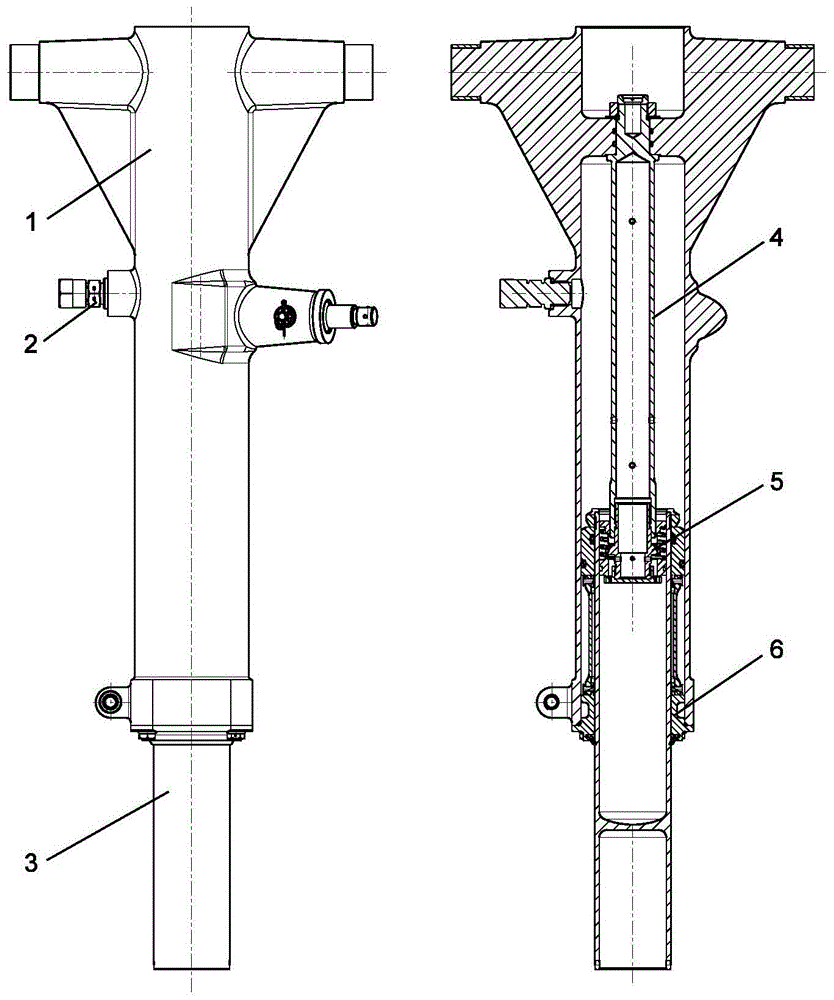
[0023] The filling medium of the buffer is aviation hydraulic oil and industrial nitrogen. like Figure 4 and Figure 7 As shown, the buffer can be divided into three working chambers: chamber A, chamber B and chamber C, wherein chamber A and chamber B communicate through the hole on the oil needle 4 . C chamber is hydraulic oil, the upper part of A chamber and B chamber is nitrogen gas, and the lower part is hydraulic oil.

[0024] The work of the buffer is divided into two cases: forward stroke and reverse stroke.

[0025] When the positive stroke works, the landing gear is affected by the ground reaction force, and the buffer inner cylinder 3 moves upward along the support ring 6. At this time, the volume of the C chamber decreases, and the valve 16 moves upward against the elastic force of the return spring 18 under the action of ...


PUM


Abstract

The invention relates to an undercarriage buffer which can exert a good buffering function in take-off, landing and sliding processes of an airplane. The undercarriage buffer comprises an outer cylinder 1, a fuel injection inflation valve 2, an inner cylinder 3, a fuel needle 4, a damping device 5 and a supporting ring 6, wherein the damping device 5 comprises a supporting piece 14, a connecting piece 15, a valve 16, a throttling valve 17, a return spring 18, a locking washer 19 and a piston ring 20, wherein the connecting piece 15 is fixed on the fuel needle 4 by threads at the upper part of the connecting piece 15; the throttling valve 17 is connectedwith the lower end of the connecting piece 15 by the threads; the supporting piece 14 is fixed at the lower end of the fuel needle 4; the locking washer 19 is used for the fixing between the supporting piece 14 and the connecting piece 15; the return spring 18 is mounted between the supporting piece 14 and the valve 16, and used for the return of the valve 16; four small holes are formed in the connecting piece 15 and act as damping holes during a forward stroke of the buffer; and four small holes are formed in the throttling valve 17, and act as damping holes during a reversal stroke of the buffer.

Description

technical field [0001] The invention belongs to the field of aeronautical engineering and relates to an aircraft landing gear buffer. Background technique [0002] Although there are many types of landing gear buffers in modern aircraft, their structures are generally complex, and landing gear buffers suitable for small aircraft are rare. With the rapid development of small aircraft, the demand for landing gear buffers suitable for small aircraft with simple structure and reliable performance is particularly urgent. [0003] The invention provides a single-cavity oil-air buffer with fixed oil holes that can meet the requirements for the use of small aircraft, and can play a good buffering role in the process of take-off, landing and taxiing of the aircraft. Contents of the invention [0004] The technical problem to be solved by the present invention is that the landing gear buffer of traditional aircraft has a complex structure, and there is no simple and reliable landin...

Claims


Application Information

Patent Timeline
Patent Type & Authority Applications(China)
IPC IPC(8): F16F9/06F16F9/34B64C25/60
CPCB64C25/60F16F9/063F16F9/34
Inventor 王永和季茂龄刁飞萌宋彦南刘双邓云生董哲
Owner HARBIN
Why Eureka
Try Eureka