Waveguide magnetic field/current sensor based on surface plasmons and device

A surface plasmon, current sensor technology, applied in the size/direction of the magnetic field, measuring device, measuring current/voltage, etc., can solve the problem of not being able to apply experimental chips, not being able to small-scale integration, optical waveguides and optical devices The classical size Large problems such as high detection sensitivity, convenient integration and arraying, and small size

Inactive Publication Date: 2015-11-04
SOUTH CHINA NORMAL UNIVERSITY
View PDF8 Cites 10 Cited by
  • Summary
  • Abstract
  • Description
  • Claims
  • Application Information

AI Technical Summary

Problems solved by technology

However, these surface plasmon-based sensors are all made of low-index-contrast dielectric materials, so the classical size of opt

Method used


Image

  • Waveguide magnetic field/current sensor based on surface plasmons and device
  • Waveguide magnetic field/current sensor based on surface plasmons and device
  • Waveguide magnetic field/current sensor based on surface plasmons and device

Examples


Embodiment 1

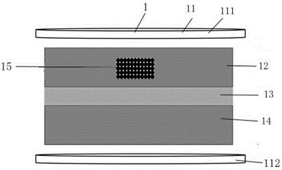
[0029] Such as figure 1 , figure 2 As shown, the surface plasmon-based waveguide magnetic field / current sensor 1 includes a magnetic field generator 11 and a first metal waveguide 12, a dielectric channel 13 and a second The metal waveguide 14, wherein the first metal waveguide 12 and the second metal waveguide 14 are provided with resonant cavities 15; the two resonant cavities 15 pass through the metal slits and dielectrics on the first metal waveguide 12 and the second metal waveguide 14 respectively. The channel 13 is connected, and the resonant cavity 15 is filled with magnetically sensitive substances. The magnetic field generator 11 includes a first pole plate 111 at the top and a second pole plate 112 at the bottom.

[0030] In this embodiment, both the first metal waveguide 12 and the second metal waveguide 14 are silver thin films, the width of the first metal waveguide 12 and the second metal waveguide 14 is 60-160 nm, the first metal waveguide 12 and the second ...

Embodiment 2

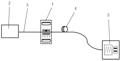
[0047] At the same time, the present invention also provides a device for applying the magnetic field / current sensor 1 described in Embodiment 1, such as figure 2 As shown, it includes a broadband light source 2, a first optical fiber link 3, a magnetic field / current sensor 1, a second optical fiber link 4 and a spectrometer 5, wherein the broadband light source 2 is connected to the input of the magnetic field / current sensor 1 through the first optical fiber link 3 The output end of the magnetic field / current sensor 1 is connected to the spectrometer 5 through the second optical fiber link 4. The broadband light source 2 is used to emit excitation light, that is, the light to be detected. The wavelength range of the excitation light is from visible red to near infrared, and the spectrometer 5 is used to observe the resonant wavelength of the transmission spectrum.


PUM

PropertyMeasurementUnit
Widthaaaaaaaaaa
Widthaaaaaaaaaa
Widthaaaaaaaaaa

Abstract

The invention relates to a waveguide magnetic field/current sensor based on surface plasmons. The provided sensor is used for detection of a magnetic field intensity or a current intensity. The magnetic field/current sensor comprises a magnetic field generator and also comprises a first metal waveguide, a dielectric medium channel and a second metal waveguide which are arranged in the magnetic field generator from top to bottom in order. A resonant cavity is formed in the first metal waveguide and/or the second metal waveguide. The resonant cavity is communicated with the dielectric medium channel through a metal seam formed in the corresponding metal waveguide. The resonant cavity is filled with magnetic sensitive substances. The magnetic field/current sensor has the following beneficial effects: a measuring space is shrank to an order of magnitude of an optical waveguide width dimension, and the magnetic field/current sensor can be made to be very small, and facilitates integration and arraying via technicians; because the magnetic field/current sensor can be prevented from influence of external conditions of light source fluctuation or the like, the magnetic field/current sensor has high detection sensitivity.

Description

technical field [0001] The invention relates to the field of magnetic field detection, in particular to a surface plasmon-based waveguide magnetic field / current sensor and a device thereof. Background technique [0002] As a basic physical quantity, magnetic field strength is valued by people no matter in the field of scientific research or in the field of industrial application. The measurement of magnetic field can be widely used in aerospace, information storage, environmental monitoring, navigation and energy survey, etc. Traditional electromagnetic sensors usually lack stability, are difficult to integrate with other structures, and cannot work in heavily polluted or harsh environments. On the other hand, due to the compact structure, high precision and high resolution optical fiber structure has been widely used in many fields. Therefore, optical fiber magnetic field sensing based on MF as a sensitive material is continuously being paid attention to. However, the st...

Claims


Application Information

Patent Timeline
IPC IPC(8): G01R33/032G01R19/00
Inventor 黄旭光苏伟衡靳小平陈銮雄
Owner SOUTH CHINA NORMAL UNIVERSITY
Why Eureka
Try Eureka