Automatic conversion device of alternating current power supply

An automatic conversion, AC power supply technology, applied in the output power conversion device, high-efficiency power electronic conversion, AC power input conversion to AC power output and other directions, can solve the problem of poor output voltage stability, power grid harmonic pollution, environmental electromagnetic pollution, etc. problems, to achieve the effect of low voltage regulation rate, overload protection and short circuit protection, and wide input range

Inactive Publication Date: 2015-11-04
HARBIN INST OF TECH
View PDF9 Cites 12 Cited by
  • Summary
  • Abstract
  • Description
  • Claims
  • Application Information

AI Technical Summary

Problems solved by technology

[0004] The purpose of the present invention is to solve the problems that the existing converter cannot fully meet the requirements of power supply parameters, the stability of the output voltage is poor, the manual operation of the voltage conversion ratio has potential safety hazards, and it is easy to cause harmonic pollution of the power grid and electromagnetic pollution of the environment. It provides A device for automatic switching of AC power

Method used


Image

  • Automatic conversion device of alternating current power supply
  • Automatic conversion device of alternating current power supply
  • Automatic conversion device of alternating current power supply

Examples


specific Embodiment approach 1

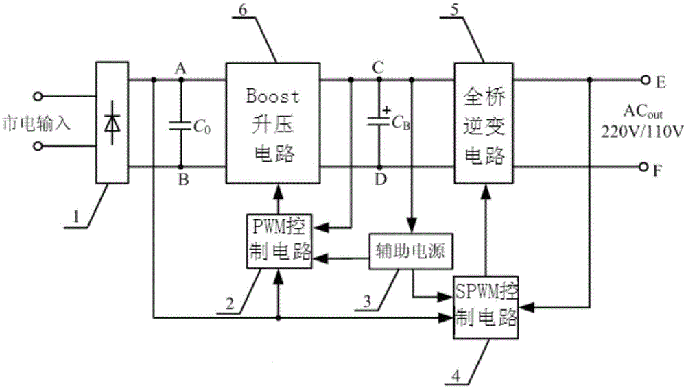
[0019] Specific implementation mode one: the following combination figure 1 Describe this embodiment, the AC power automatic conversion device described in this embodiment includes two-stage circuits, the front stage is a Boost circuit with APFC function; the latter stage is a full-bridge inverter that can automatically switch the output according to the input voltage level The circuit specifically includes a diode bridge rectifier circuit 1, a PWM control circuit 2, an auxiliary power supply 3, an SPWM control circuit 4, a full-bridge inverter circuit 5 and a Boost circuit 6;

[0020] The mains input is rectified by the diode bridge rectifier circuit 1 and then output. The two input terminals of the boost circuit 6 are respectively connected to the output terminal A and the output terminal B of the diode bridge rectifier circuit 1, and the output terminal A of the diode bridge rectifier circuit 1 A filter capacitor C is connected in parallel with the output terminal B 0 , th...

specific Embodiment approach 2

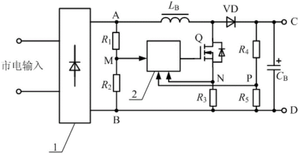
[0025] Specific implementation mode two: the following combination Figure 2-Figure 4 Describe this embodiment, this embodiment will further illustrate Embodiment 1, and the Boost voltage boosting circuit 6 includes a resistor R 1 , resistance R 2 , inductance L B , switch tube Q, resistor R 3 , diode VD, resistor R 4 and resistor R 5 ;

[0026] Resistance R 1 One end of the diode bridge rectifier circuit 1 is connected to the output terminal A, and the resistance R 2 One end of the diode bridge rectifier circuit 1 is connected to the output terminal B, and the resistance R 1 the other end and the resistor R 2 The other end of is connected to sampling point M;

[0027] Inductance L B One end of the diode bridge rectifier circuit 1 is connected to the output terminal A, and the inductor L B The other end is connected to the drain of the switch tube Q, and the resistor R 3 One end of the diode bridge rectifier circuit 1 is connected to the output terminal B, and the ...

specific Embodiment approach 3

[0034] Specific implementation mode three: the following combination Figure 5 Describe this embodiment mode, this embodiment mode will further illustrate Embodiment 1, and the full-bridge inverter circuit 5 includes a resistor R S , switch tube Q 1 , switch tube Q 2 , switch tube Q 3 , switch tube Q 4 , inductance L and capacitance C;

[0035] The output terminal C of the boost circuit 6 is connected to the switch tube Q at the same time 1 The drain and switch Q 2 The drain of the boost circuit 6 is connected to the output terminal D of the resistor R S One end of the resistor R S The other end of the switch tube Q 3 source and switch Q 4 The source is connected as the sampling point O at the same time, the switch tube Q 1 source and switch Q 3 The drain connection of the node G, the switch Q 2 source and switch Q 4 The drain of the inductor L is connected to the output terminal F, one end of the inductor L is connected to the node G, the other end of the inducto...


PUM


Abstract

The invention relates to an automatic conversion device of an alternating current power supply, which belongs to the field of power electronics and aims to solve the problems that the requirement of power supply parameters of the power supply cannot be completely satisfied by the traditional converter, the output voltage stability is poor, and harmonic pollution to a power grid and magnetic pollution to an environment are easily caused due to potential safety hazard existing in manual operation of voltage ratio. The automatic conversion device comprises two stages of circuits, wherein the front stage is a Boost circuit having active power factor correction (APFC) function, the rear stage is a full-bridge inversion circuit, the full-bridge inversion circuit can be used for automatically switching output according to the grade of an input voltage, the Boost circuit can be used for boosting a wide-range alternating current into 400V direct current for output, and the full-bridge inversion circuit is used for automatically switching output voltage and frequency according to the input voltage. By the automatic conversion device, automatic switching of sine alternating current voltage between 220V / 50Hz and 110V / 60Hz can be achieved. The automatic conversion device is used for automatic switching of normal mains supply between 110V / 60Hz and 220V / 50Hz.

Description

technical field [0001] The invention relates to an AC power automatic conversion device, which belongs to the field of power electronics. Background technique [0002] With the development of economy and technology, the process of globalization is accelerating, and a series of problems have also emerged. Internationally, there are mainly two kinds of civilian alternating current, 110V / 60Hz and 220V / 50Hz, so there are two kinds of power supply systems for civilian appliances. [0003] At present, the power adapters of some high-value electrical appliances adopt switching power supply technology, which can work in a wide voltage range of AC85V ~ 240V, but most household appliances still have strict restrictions on the power supply system of AC power supply. An additional step-up or step-down AC power converter is required. Conventional converters use manual selection of 2:1 or 1:2 power frequency transformers. Although this kind of converter is simple and reliable, it is not...

Claims


Application Information

Patent Timeline
Patent Type & Authority Applications(China)
IPC IPC(8): H02M5/458H02M1/42H02M3/156
CPCY02B70/10
Inventor 杨世彦杨威尹延松韩基业
Owner HARBIN INST OF TECH
Why Eureka
Try Eureka