
Single crystal extraction method

An extraction method, single crystal technology, applied in the field of single crystal extraction, can solve problems such as single crystal slip dislocation, dislocation, crystal dislocation, etc., and achieve the effect of improving yield

Active Publication Date: 2015-11-11
GLOBALWAFERS JAPAN
View PDF13 Cites 6 Cited by
  • Summary
  • Abstract
  • Description
  • Claims
  • Application Information

AI Technical Summary

Problems solved by technology

[0011] However, in the single crystal extraction method disclosed in JP-A-2012-36042, in order to form the lower end of the crystal into a convex shape, it is necessary to stop the lifting of the crucible and maintain the state of stopping the crystal extraction for a predetermined time, so it cannot be compared with Significantly shortens the time compared to the case of implementing the conventional tail forming process
[0012] In addition, since the determination of whether an appropriate convex shape is formed at the lower end of the crystal is performed by detecting the change in the apparent weight of the single crystal, if the accuracy of weight measurement is low, an appropriate convex shape cannot be obtained, and there is a risk of dislocation in the crystal.
That is, when the formation of the convex shape is insufficient, a sharp temperature change occurs at the lower end of the crystal, and slip dislocation may occur in the single crystal. In the case of an extremely sharp convex state, the melt is supercooled. risk of dislocation

Method used

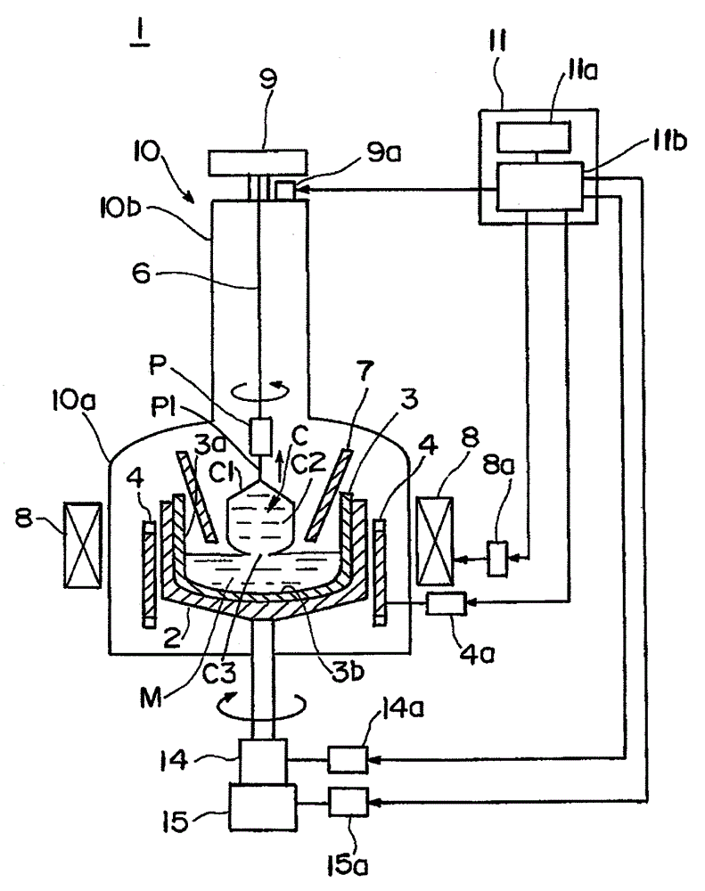
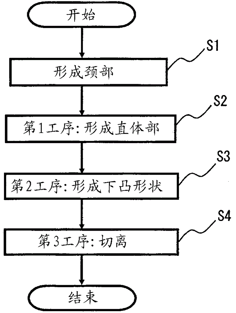

Image

  • Single crystal extraction method
  • Single crystal extraction method
  • Single crystal extraction method

Examples


Embodiment

[0054] The single crystal extraction method related to the present invention will be further described based on examples. In this example, single crystal extraction was performed using the single crystal extraction apparatus described in the foregoing embodiments, and the extracted crystal was verified.

[0055] Specifically, after the first step of forming the straight body part, in the second step (when the solidification rate is 0.77), which is the final step of forming the straight body part, according to the magnetic flux density, crystal extraction speed, crystal rotation speed, crucible Examples 1-8 and Comparative Examples 1-13 are classified according to each condition of rotation speed. Then, with regard to the extracted crystal, it was judged whether or not extraction can be performed without dislocation, whether or not there is deformation, and the length of the convex shape. The diameter of the single crystal to be cultivated is 390 mm, and 350 kg of silicon crys...


PUM


Abstract

The single crystal extraction method is used for shortening the extraction time from the forming of a straight body part to crystal excision from a meltwater, extracting single crystal and improving a rate of finished products. The method comprises a first process, a second process and a third process. The first process forms the straight body part (C2), and the second process is behind the first process. In the final process of forming the straight body part, a lower protruded shape (C3) protruded downwards is formed at the lower end of the crystal, and the third process is configured to cut the lower protruded shape formed in the second process from the silicon meltwater. In the second process, the field density of the horizontal magnetic field is controlled lower than the first process in the range of 800 to 1000 gausses, the crystal extract speed is controlled lower than the first process in the range of 0.2 to 0.5 mm / min, the crystal rotation speed is controlled lower than the first process in the range of 1 to 3 rpm, and the crucible rotation speed is controlled in the range of 0.5 to 5 rpm.

Description

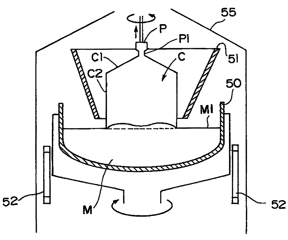
technical field [0001] The present invention relates to a single crystal extraction method in which a single crystal is grown and a single crystal is extracted according to the Czochralski single crystal growth method (hereinafter referred to as "CZ method"). Background technique [0002] For growing silicon single crystals, the CZ method is widely used. In this method, as Figure 4 As shown, silicon melt M is formed in a quartz glass crucible 50 (hereinafter simply referred to as crucible 50 ) by the heat of a side heater 52 in a melting furnace 55 . Then, within the range surrounded by the radiation shield 51, the seed crystal P is brought into contact with the surface M1 of the molten liquid M, the crucible 50 is rotated, and the seed crystal P is extracted upward while rotating in the opposite direction, thereby A single crystal C is formed at the lower end of the seed crystal P. [0003] Specifically, necking down of the end portion of the melted seed crystal P is per...

Claims


Application Information

Patent Timeline
IPC IPC(8): C30B29/06C30B15/20
Inventor 安部吉亮小松秀央
Owner GLOBALWAFERS JAPAN
Learn More