Ramie banding and splitting device and method

A ribbon forming and ramie technology, which is applied in the field of ramie ribbon forming and fiber opening devices, can solve the problems of high labor intensity, high noise, and low production rate of long fibers in the subsequent process, and achieve the effects of saving labor costs and improving production efficiency

Inactive Publication Date: 2015-11-11
DAZHU GOLDEN BRIDGE RAMIE
View PDF0 Cites 1 Cited by
  • Summary
  • Abstract
  • Description
  • Claims
  • Application Information

AI Technical Summary

Problems solved by technology

This method of ramie production is discontinuous and is not suitable for large-scale production. In addition, the straight ramie fiber bundles are first disturbed, and then smoothed by manual labor and equipment, which wastes a lot of manpower and materia

Method used


Image

  • Ramie banding and splitting device and method

Examples


Embodiment 1

[0030] Example 1 - Lean Feed of Ramie

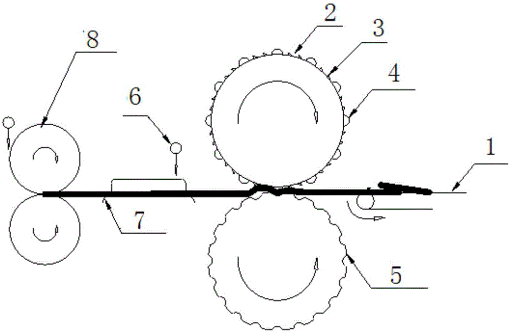
[0031] Taking thinly fed ramie as an example, the above-mentioned ramie belt forming and fiber opening device and method are used to realize the belt forming and fiber opening of ramie. The specific implementation method is: in the described ramie belt fiber opening device, the tooth ends of the ratchets 3 are indented by 2mm compared with the peeling bar 4, the circumferential ratchet distance is 20mm, and the axial ratchet distance is 15mm; the groove roller 5 The diameter of the groove is 10mm, the diameter of the groove roller 5 and the ratchet roller 2 is 400mm, and the gap between the groove roller 5 and the ratchet roller 2 is 0mm. The traction roller group 8 is provided with 3 pairs, and the gap between the pairs is 300 mm; the draft ratio of 1-2 pairs is 3 times, and the draft ratio of 2-3 pairs is 1.1 times.

[0032] The specific implementation process is: put the degummed ramie on the conveyor belt 1 step by step in a stacked...

Embodiment 2

[0033] Example 2 - Mass feed of ramie

[0034] Taking heavy-feeding ramie as an example, the belt forming and fiber opening of ramie are realized by using the above-mentioned ramie belt forming and fiber opening device and method. The specific implementation method is: in the described ramie belt fiber opening device, the tooth ends of the ratchets 3 are indented by 20mm compared with the peeling bar 4, the circumferential ratchet distance is 50mm, and the axial ratchet distance is 50mm; the groove roller 5 The diameter of the groove is 30mm, the diameter of the groove roller 5 and the ratchet roller 2 is 600mm, and the gap between the groove roller 5 and the ratchet roller 2 is 15mm. The traction roller group 8 is provided with 7 pairs, and the gap between the pairs is 600 mm; the draft ratio of 1-2 pairs is 6 times, and the draft ratio of 2-7 pairs is 1.5 times.

[0035] The specific implementation process is: put the degummed ramie on the conveyor belt 1 step by step in a ...


PUM

PropertyMeasurementUnit
Diameteraaaaaaaaaa
Diameteraaaaaaaaaa

Abstract

The invention discloses a ramie banding and splitting device and method. The device comprises a conveyer belt, a transition groove, flushing devices, traction roller sets and a banding device. The banding device comprises ratchet rollers and groove rollers. The circumferential surface of each ratchet roller is provided with ratchets and stripping strips. Axial grooves are formed in the circumferential surface of each groove roller. Each traction roller set is composed of two rubber rollers or the groove rollers with clean surfaces in the mode of being distributed symmetrically about the conveying face of the conveyer belt. The conveyer belt is sequentially provided with the banding device, the flushing devices, the transition groove and the traction roller sets in the ramie conveying direction. Under the combined action of the conveyer belt and traction rollers, degummed ramie fibers penetrate through the banding device formed by the ratchet rollers and the groove rollers, and the banding device produces the fast and slow fibers so that bands can be formed. The ramie banding and splitting device always keeps the fibers straight in the ramie banding and splitting processes, ramie is finished and dragged, manual smoothing is not needed, production efficiency is improved, a great deal of labor cost is saved, and the ramie can be produced continuously in a large-scale mode.

Description

technical field [0001] The invention relates to the technical field of ramie production, in particular to a ramie belt forming and fiber opening device and method. Background technique [0002] Ramie is one of the important textile raw materials, which can be used for ramie spinning only after being degummed and made into dry hemp. For a long time, most of the factories use hemp kneading machines to implement fiber opening and degumming processing to the boiled ramie fiber raw materials (hereinafter referred to as raw materials). The basic principle is: the shift fork on the driving shaft of the machine intermittently drives the hemp hammer to lift upwards, and then falls freely to impact the raw materials in the lower tray (in a state of continuous rotation). The raw materials are constantly turned in the tray, so that the processed raw materials are subjected to repeated hammering, so as to achieve the purpose of fiber opening and degumming. This mode of ramie production...

Claims


Application Information

Patent Timeline
IPC IPC(8): D01B5/00D01B5/06
Inventor 秦大祥彭位芝
Owner DAZHU GOLDEN BRIDGE RAMIE
Why Eureka
Try Eureka