
Three-station time-difference-measuring stereoscopic positioning method

A technology of stereotaxic positioning and time difference, applied in positioning, measuring devices, radio wave measuring systems, etc., can solve the problem that the position of the radiation source cannot be uniquely determined, achieve good engineering application prospects, save the process of solving analytical solutions, and have strong operability Effect

Inactive Publication Date: 2015-11-11
10TH RES INST OF CETC
View PDF3 Cites 19 Cited by
  • Summary
  • Abstract
  • Description
  • Claims
  • Application Information

AI Technical Summary

Problems solved by technology

[0010] The task of the present invention is to provide an easy-to-understand, easy-to-calculate, and highly operable method for the situation where the position of the radiation source cannot be uniquely determined in the three-station time difference stereotaxic positioning, based on the known six side lengths to judge whether it can form four sides Analytical solution method of volume theory to solve the tedious problem of solving hyperboloid equations

Method used


Image

  • Three-station time-difference-measuring stereoscopic positioning method
  • Three-station time-difference-measuring stereoscopic positioning method
  • Three-station time-difference-measuring stereoscopic positioning method

Examples


Embodiment Construction

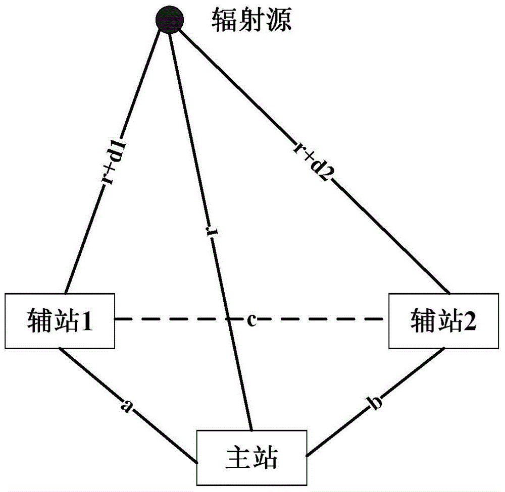
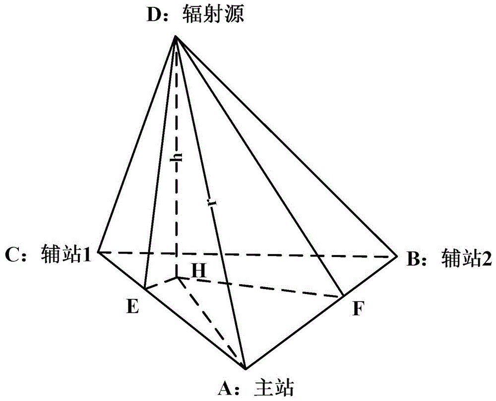
[0017] refer to figure 1 . In the three-station time difference stereotaxic positioning method described below, the three stations include a main station and two auxiliary stations, and it is required that they cannot be in a straight line. The three-station time difference stereotaxic positioning system simultaneously measures the time difference Δt between the arrival of external radiation at the main station and the auxiliary station 1 1 , the time difference Δt between the main station and the auxiliary station 2 2 . Now assume that the distance from the radiation source to the main station is r, then the distance from the radiation source to the auxiliary station 1 is r+d 1 , the distance from the radiation source to the auxiliary station 2 is r+d 2 , where d 1 = cΔt 1 , d 2 = cΔt 2, c is the speed of light. First, use the distance (a, b, c) between the three stations and the two distance differences d obtained by multiplying the measured time difference by the s...


PUM


Abstract

The invention provides a three-station time-difference-measuring stereoscopic positioning method and aims to provide a method of rapidly acquiring all possible three-dimensional position solutions of a radiation source, wherein the solutions satisfy time difference measuring conditions. The method is achieved through the following schemes that by means of six parameters including the distances among three stations, two distance differences acquired by multiplying measured time difference values with the light velocity and the distance variable r between the radiation source and a primary station, the value range of r is acquired by using the constraining condition on whether the three stations and the radiation source can form a tetrahedron; a certain specific value in the value range of the r is given at will; and by means of the specific value and the given geographical positions of the three stations, the vertical projection coordinates of the radiation source on the plane where the three stations are located are acquired through a three-variable linear equation group; the distance h between the radiation source to the vertical projection is further calculated; and finally the radiation source coordinates XD in an earth-centered earth-fixed (ECEF) rectangular coordinate system are given in an analytic solution way through X(H) and h. By means of the method, tedious analytic solutions and discussions on the real root existence thereof are reduced.

Description

technical field [0001] The invention relates to a three-station passive positioning system of a radar detection system. When passive radar time difference positioning only obtains two sets of time difference data, a method for quickly providing all possible positions of a radiation source in a three-dimensional space. Background technique [0002] In the field of wireless communication, the problem of target source location has been paid more and more attention by scientists. Target source localization has a wide range of applications in real life. Passive positioning is to passively receive the signal of the radiation source, and determine the position of the radiation source according to the arrival time and direction of the radiation source signal. Among them, the passive direction finding positioning is the earliest and most studied positioning technology, derived from this The multi-station cross-location and single-station multi-point cross-location are the important ...

Claims


Application Information

Patent Timeline
IPC IPC(8): G01S5/10
CPCG01S5/10
Inventor 宋文彬乔文昇马霞任然李学英
Owner 10TH RES INST OF CETC
Learn More