Insulated Gate Bipolar Transistor (IGBT) driver interlock circuit with power-on time delay function

A technology of interlocking circuit and delay circuit, which is applied in the direction of output power conversion device and electrical components, etc., can solve the problems that the output impact level of the drive module affects the IGBT switch, the initial power-on instability, etc., so as to prevent the IGBT short-circuit fault , simple topology, and the effect of avoiding short-circuit faults

Inactive Publication Date: 2015-11-11
ZT YUPIN TECH CO LTD
View PDF3 Cites 3 Cited by
  • Summary
  • Abstract
  • Description
  • Claims
  • Application Information

AI Technical Summary

Problems solved by technology

At present, the existing IGBT drive circuit has the problem that the initial power-on is un

Method used


Image

  • Insulated Gate Bipolar Transistor (IGBT) driver interlock circuit with power-on time delay function
  • Insulated Gate Bipolar Transistor (IGBT) driver interlock circuit with power-on time delay function
  • Insulated Gate Bipolar Transistor (IGBT) driver interlock circuit with power-on time delay function

Examples


Embodiment

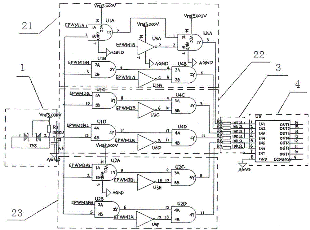
[0026] The working principle diagram of the circuit of this embodiment is as follows figure 1 As shown, it consists of sequentially connected delay circuit module 1, non-logic circuit module, several resistors 3, and inverting driver 4, and the driving signal sent by the interlock circuit formed by the non-logic circuit module passes through the resistor R2 and the resistor R2 respectively. R3, resistor R4, resistor R5, resistor R6, and resistor R7 are connected to the input end of the inverting driver 4.

[0027] The delay circuit module 1 is composed of a power supply, a voltage regulator tube TVS, a resistor R1 and a capacitor C1 to form a delay circuit. The delay time and the output level of the delay circuit change slowly from low to high, and output after a certain period of time. Stable supply voltage.

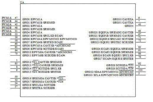
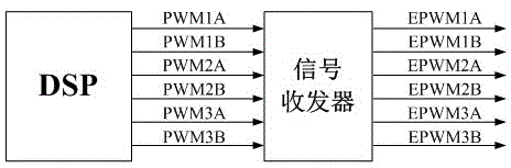
[0028] Such as figure 2 The pin diagram of the DSP chip is shown, and the block diagram of the driving signal sent by the DSP chip through the signal transceiver is ...


PUM


Abstract

The invention discloses an IGBT driver interlock circuit with a power-on time delay function, including a time delay circuit module 1, an NAND logic circuit module, a plurality of resistors 3s, an inverting drive 4 which are successively connected; the NAND logic circuit module includes a plurality of NAND logic circuit groups composed of an upper pipe and a lower pipe. According to the invention, a drive signal which is sent by a Digital Signal Processor (DSP) chip is subject to a certain time delay, and then is output to a drive board for driving an IGBT module so as to enable the IGBT to have a reliable turn-off within the time period. The circuit is also provided with an interlock circuit, and constitutes a logic relationship with an NAND gate chip such that once one signal turns to be a high level signal, another signal will be a low level signal,thereby guaranteeing the upper and lower pipes of the IGBT are not powered on at the same time and preventing short circuit breakdown of the IGBT. The IGBT driver interlock circuit with the power-on time delay function precludes the short circuit breakdown of the IGBT, effectively protects the bridge arm of the IGBT, and increases the reliability of the IGBT driver circuit.

Description

technical field [0001] The invention relates to a drive circuit, in particular to an IGBT drive interlock circuit with a power-on delay function. Background technique [0002] Insulated gate bipolar transistor (InsulatedGateBipolarTransistor, referred to as IGBT), which integrates the advantages of bipolar power transistor and power MOSFET, has the advantages of voltage control, large input impedance, low driving power, simple control circuit, small switching loss, and fast on-off speed. With the advantages of high speed and high operating frequency, it has been widely used in the fields of converters, frequency converters, switching power supplies, etc., and its role is particularly significant in high-power circuits. Therefore, the driving circuit of the IGBT is a key link in the operation of the entire device. [0003] Since the topology circuit composed of IGBTs often exists in the form of bridge arms, its driving circuit must prevent the occurrence of short-circuit and...

Claims


Application Information

Patent Timeline
IPC IPC(8): H02M1/38
Inventor 冯中魁熊俊峰徐小飞马晓聪迟震
Owner ZT YUPIN TECH CO LTD
Why Eureka
Try Eureka