Vibration compensation control system for rotor of bearing-less asynchronous motor based on torque inverse

A technology of asynchronous motor and compensation control, which is applied in the control system, vector control system, motor generator control, etc. It can solve the problems of uneven processing accuracy of materials, unbalanced vibration of rotors, and affecting the control accuracy of rotor suspension.

Inactive Publication Date: 2015-11-11
HENAN UNIV OF SCI & TECH
View PDF4 Cites 11 Cited by
  • Summary
  • Abstract
  • Description
  • Claims
  • Application Information

AI Technical Summary

Problems solved by technology

As a rotary drive motor, due to uneven material, processing accuracy, assembly errors, etc., there will inevitably be a certain degree of eccentricity of the rotor mass, which will generate an unbalanced excitation force at the same frequency as the rotational speed during rotation, resulting in unbalanced vibration of the rotor , affecting the suspension control accuracy of the rotor
[0003] After searching the existing literature and patents, it is found that there are few research results at home and abroad on the rotor unbalance vibration control technology of bearingless motors. The existing research mainly focuses on the control of synchronous bearingless motors, and there is no rotor displacement. Effective decomposition is basically to compensate the unbalanced excitation force on the basis of traditional static magnetic field oriented control

Method used


Image

  • Vibration compensation control system for rotor of bearing-less asynchronous motor based on torque inverse
  • Vibration compensation control system for rotor of bearing-less asynchronous motor based on torque inverse
  • Vibration compensation control system for rotor of bearing-less asynchronous motor based on torque inverse

Examples


Embodiment Construction

[0050] In order to make the content of the present invention more obvious and understandable, the present invention will be described in detail below in conjunction with specific embodiments.

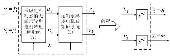
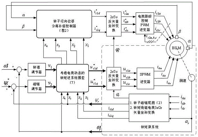
[0051] In order to improve the speed control performance of the bearingless asynchronous motor, realize the precise control of the motor flux linkage, and provide conditions for the high-performance decoupling control of the magnetic levitation system, the stator current dynamic differential equation of the torque system is introduced, and the rotor flux linkage oriented inversion is used for the torque system. The dynamic decoupling control of the system realizes the dynamic decoupling between the electromagnetic torque control and the rotor flux linkage control, and performs the air-gap magnetization of the torque system required for the magnetic levitation decoupling operation on the basis of the inverse dynamic decoupling control of the torque system. chain information.

[0052] Dur...


PUM


Abstract

The invention discloses a vibration compensation control system for a rotor of a bearing-less asynchronous motor based on torque inverse. The system comprises an inverse dynamic decoupling torque control system and a rotor radial displacement separation and unbalanced force compensation control system, wherein the inverse dynamic decoupling torque control system is as follows: a torque inverse system is connected to the front of an original system in series to form two linear subsystems of a rotor flux and rotating speed, and a flux regulator and a rotating speed regulator are respectively correspondingly connected to an output end of the original system and an input end of the inverse system to form a closed loop system; the rotor radial displacement separation and unbalanced force compensation control system decomposes a rotor radial displacement to a random displacement and an unbalanced vibration displacement and then respectively adjusts to obtain random displacement control force and unbalanced force compensation control force, and the random displacement control force and the unbalanced force compensation control force are compared with a unilateral electromagnetic pull compensation signal and are subjected to force/current conversion to obtain comprehensive magnetic suspension control current, the unbalanced vibration compensation control on the inverse dynamic decoupling control of the torque system is implemented, and the rotor suspension operation control precision is improved.

Description

technical field [0001] The invention relates to the technical field of drive control of special AC motors, is especially suitable for high-precision magnetic suspension operation control of bearingless asynchronous motors, and is a practical rotor unbalanced vibration control system based on torque inversion. Background technique [0002] Bearingless motor is based on the similarity between magnetic bearing and AC motor stator structure. It is a new type of motor suitable for high-speed operation developed in recent years. It has broad application prospects in aerospace, material sealing transmission, advanced manufacturing and other fields. As a rotary drive motor, due to uneven material, processing accuracy, assembly errors, etc., there will inevitably be a certain degree of eccentricity of the rotor mass, which will generate an unbalanced excitation force at the same frequency as the rotational speed during rotation, resulting in unbalanced vibration of the rotor , affect...

Claims


Application Information

Patent Timeline
Patent Type & Authority Applications(China)
IPC IPC(8): H02P21/00H02P21/08H02P21/12H02P27/06
Inventor 卜文绍张松灿李晓强肖隽亚路春晓刘磊坡李劲伟乔岩茹王国强
Owner HENAN UNIV OF SCI & TECH
Why Eureka
Try Eureka