Supercharge Your Innovation With Domain-Expert AI Agents!

Self-calibrated driving circuit of light-emitting diode (LED) corridor lighting system

A lighting system and driving circuit technology, which is applied to lighting devices, lamp circuit layout, electric light sources, etc., can solve problems such as EMI interference and low power utilization, and achieve the effects of reduced power consumption, low power consumption, and simple circuits

Active Publication Date: 2015-11-11
常州市海铂尔电子科技有限公司
View PDF4 Cites 0 Cited by
  • Summary
  • Abstract
  • Description
  • Claims
  • Application Information

AI Technical Summary

Problems solved by technology

[0003] LED drive circuits can be divided into two categories: (1) Voltage drive: such as low-voltage drive, transition voltage drive, high-voltage drive and mains drive, among which low-voltage drive is mainly used in LED flashlights, LED emergency lights and other fields; Transition voltage drive is mainly used in LED miner's lamp; high-voltage drive is only used in solar garden lights and motor vehicle lighting systems; direct drive of mains power LED has broad development prospects in semiconductor lighting; (2) current drive: such as linear analog dimming The current is linearly adjustable, the current accuracy is high, and there is no EMI (electromagnetic interference), but the circuit is always in the working state, and the power utilization rate is low; currently the most commonly used is PWM dimming drive, by adjusting the PWM duty cycle, the circuit conduction Alternate open and closed cycles, which not only prolongs the service life of the drive circuit, but also improves power efficiency, but there is EMI interference

Method used


Image

  • Self-calibrated driving circuit of light-emitting diode (LED) corridor lighting system
  • Self-calibrated driving circuit of light-emitting diode (LED) corridor lighting system

Examples


Embodiment 1

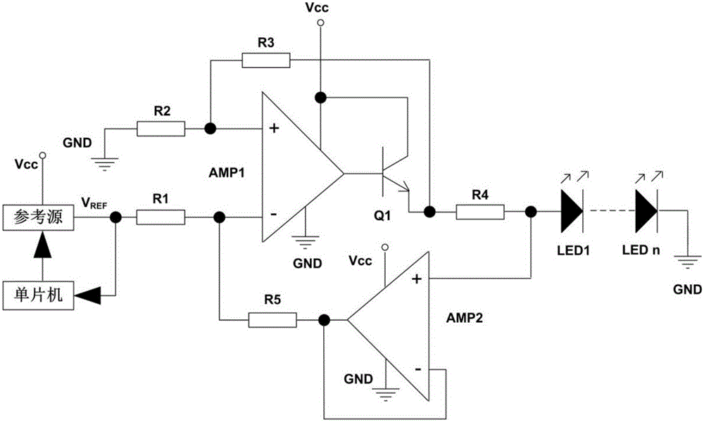
[0025] figure 1 It is a schematic circuit diagram of the driving circuit of the self-calibrating LED corridor lighting system described in Embodiment 1 of the present invention. It can be seen from the figure that the driving circuit of the self-calibrating LED corridor lighting system includes: a reference source for providing a reference voltage for the LED corridor lighting system, a first operational amplifier AMP1, a second operational amplifier AMP2, a first resistor R1, a second resistor R2, a third resistor R3, a fourth resistor R4, a fifth resistor R5, a transistor Q1, a plurality of LED lamps connected in series in the same direction, and a single chip microcomputer.

[0026] The same input end of the first operational amplifier AMP1 is respectively connected to one end of the second resistor R2 and one end of the third resistor R3, and the other end of the second resistor R2 is grounded; the inverting input end of the first operational amplifier AMP1 passes through ...

Embodiment 2

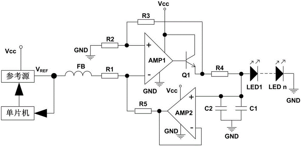
[0031] The driving circuit of the self-calibrating LED corridor lighting system provided in this embodiment is different from Embodiment 1 in that the driving circuit of the self-calibrating LED corridor lighting system also includes a magnetic bead FB, such as figure 2 As shown, one end of the magnetic bead FB is connected to the output end of the reference source, and the other end is connected to one end of the first resistor R1, which has the advantages of suppressing high-frequency noise and spike interference at the output end of the reference source and absorbing electrostatic pulses.

[0032]As another implementation of this embodiment, the drive circuit of the self-calibrating LED corridor lighting system further includes a first capacitor C1 and a second capacitor C2, and the other end of the fourth resistor R4 passes through one end of the first capacitor C1, the second capacitor One end of the second capacitor C2 is connected to the non-inverting input end of the f...


PUM


Abstract

The invention discloses a self-calibrated driving circuit of a light-emitting diode (LED) corridor lighting system. The self-calibrated driving circuit comprises a reference source, a first operational amplifier, a second operational amplifier, a first resistor, a second resistor, a third resistor, a fourth resistor, a fifth resistor, a transistor, a plurality of LED lamps connected in series in a same direction and a singlechip, wherein a forward input end of the first operational amplifier is connected with one end of the second resistor and one end of the third resistor respectively, the other end of the second resistor is grounded, a reverse input end of the first operational amplifier is connected to an output end of the reference source via the first resistor, the output end is connected to a base of the transistor, the singlechip is connected between the output end of the reference source and the reference source, a collector of the transistor is connected to a power supply end, an emitter of the transistor is connected to the other end of the third resistor and one end of the fourth resistor respectively, and the singlechip is used for detecting a reference voltage output from the output end of the reference source and feeding back to the reference source. The self-calibrated driving circuit has the advantages of self calibration, low power consumption and low cost.

Description

technical field [0001] The invention relates to the field of intelligent lighting, and more specifically, the invention relates to a driving circuit of a self-calibrating LED corridor lighting system. Background technique [0002] The corridor lighting system initially used incandescent lamps. Incandescent lamps are prone to heat and cause a lot of energy loss. Incandescent lamps are gradually replaced by energy-saving lamps. Energy-saving lamps have relatively high luminous efficiency and good energy-saving effect. At present, the corridor lighting system also uses LED lights, which have pure colors, good energy saving effects and long service life. As for the induction control technology part of the corridor lighting system, it mainly uses sound induction or infrared induction, that is, to light the corridor through sound or temperature infrared induction, which can not only meet the corridor lighting at night, but also save energy to the greatest extent. [0003] LED dr...

Claims


Application Information

Patent Timeline
IPC IPC(8): H05B37/02
Inventor 董佳瑜董春保
Owner 常州市海铂尔电子科技有限公司
Features
  • R&D
  • Intellectual Property
  • Life Sciences
  • Materials
  • Tech Scout
  • Unparalleled Data Quality
  • Higher Quality Content
  • 60% Fewer Hallucinations
Learn More