Laser scanning observation device and laser scanning method

A laser scanning and observation device technology, applied in the field of laser scanning, can solve the problems of large size, high cost, and difficulty in installing optical systems, and achieve the effect of high-precision observation and wide field of view

Inactive Publication Date: 2015-11-11
SONY CORP
View PDF8 Cites 33 Cited by
  • Summary
  • Abstract
  • Description
  • Claims
  • Application Information

AI Technical Summary

Problems solved by technology

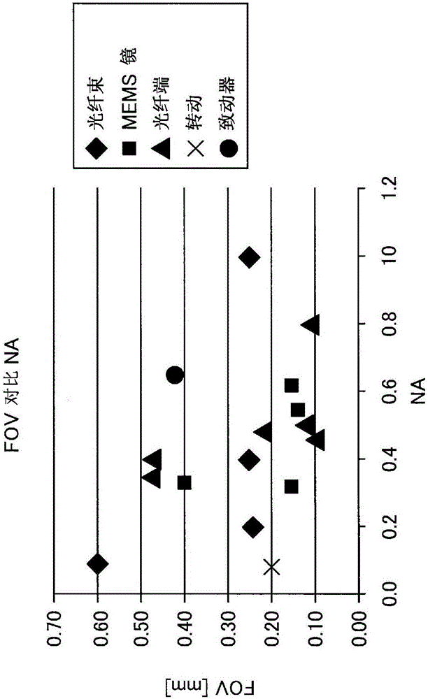
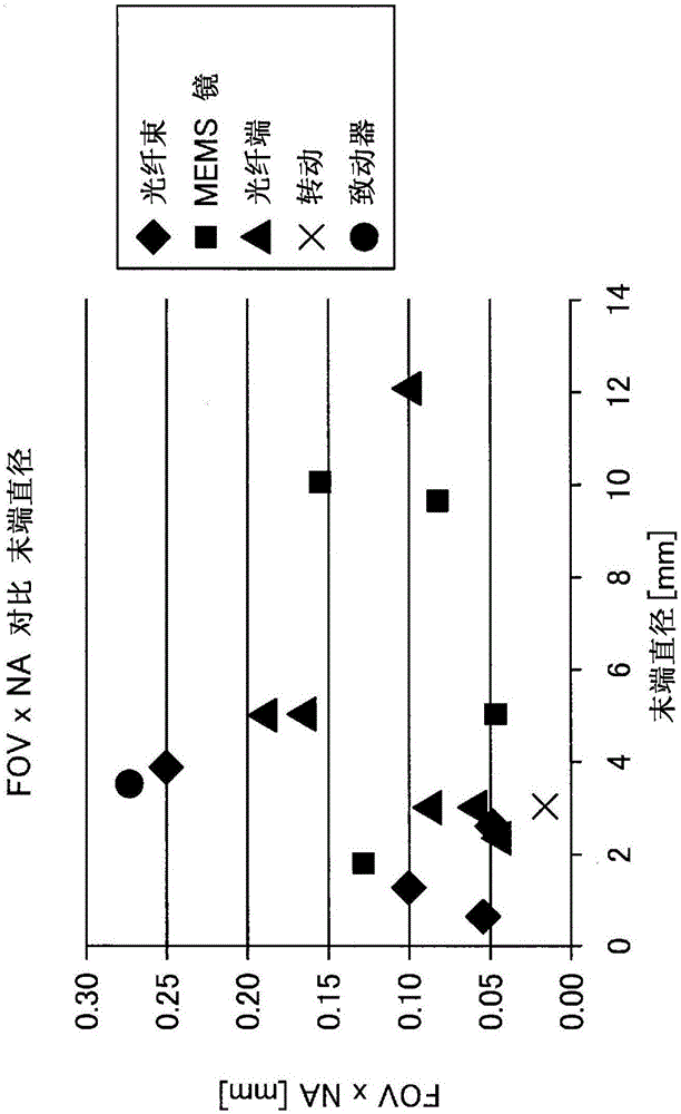
However, in order to achieve a wider field of view and a larger numerical aperture, it is usually necessary to make the optical system complex, and thus create problems of large size and high cost
Specifically, in devices that need to have smaller dimensions in terms of their application, such as probes or endoscopes, it is difficult to install complex optical systems, and thus achieve both a wider field of view and a larger numerical aperture construction is difficult to implement

Method used


Image

  • Laser scanning observation device and laser scanning method
  • Laser scanning observation device and laser scanning method
  • Laser scanning observation device and laser scanning method

Examples


no. 2 example

[0066] 4. Modify the instance

[0067] 4-1. Configuration in which the scanning unit includes a plurality of objective lenses

[0068] 4-1-1. Configuration in which the optical path changing element is a polarization beam splitter

[0069] 4-1-2. Structure in which the optical path changing element is a MEMS mirror

[0070] 4-1-3. Configuration in which the scanning unit includes an optical path branching element

[0071] 4-1-4. Configuration in which incident position of laser light relative to tube is fixed

[0072] 4-2. Other structures

[0073] 4-2-1. Configuration in which scanning unit has another rotation axis direction

[0074] 4-2-2. Modification of arrangement of objective lens in longitudinal direction of tube

[0075] 5. Construction of aberration correction unit

[0076] 5-1. Correction of astigmatism

[0077] 5-1-1. Cylindrical meniscus lens pair

[0078] 5-1-2. Cylindrical meniscus lens

[0079] 5-1-3. Cylindrical plano-concave lens

[0080] 6. Includi...


PUM


Abstract

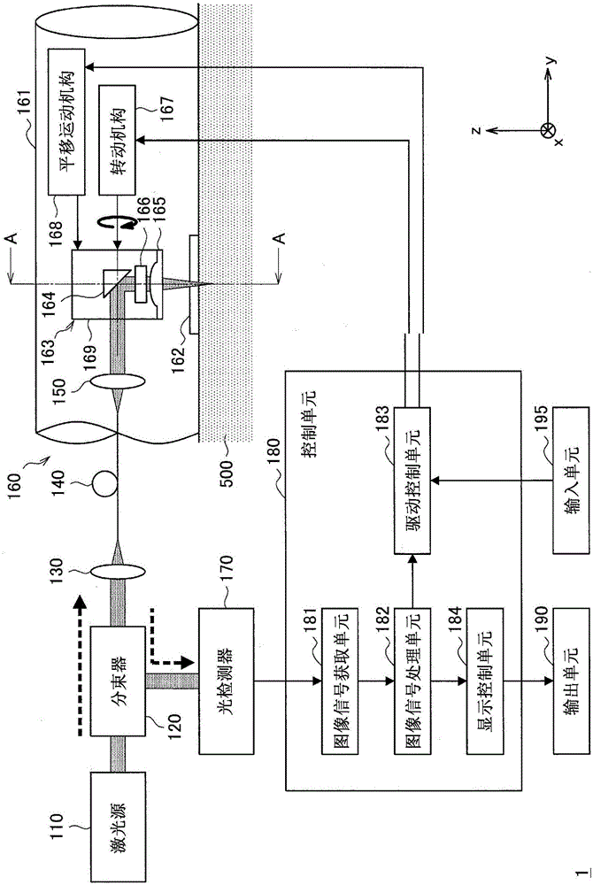
Provided is a laser scanning observation device which comprises: a window portion which is provided in one area of a housing and comes into contact with or close to an object to be observed; an objective lens that converges laser light to the object to be observed through the window portion; a light path changing element which changes the direction of travel of the laser light that has been guided inside the housing toward the window portion; an astigmatism correction element which is provided at a front stage of the window portion and corrects astigmatism that occurs when the laser light is converged to the object to be observed, and a rotation mechanism which rotates at least the light path changing element in a vertical rotation axis with respect to an incidence direction of the laser light into the window portion such that the laser light scans the object to be observed. The astigmatism correction element corrects the astigmatism in a correction amount that corresponds to change in the astigmatism that occurs along with the change in the observation depth which is the depth of a converging position of the laser light in the object to be observed.

Description

technical field [0001] The present disclosure relates to a laser scanning observation device and a laser scanning method. Background technique [0002] For techniques to observe objects with high resolution, there are laser scanning microscopy devices. A laser scanning microscope can scan an object with laser light, by applying laser light to the object and detecting its transmitted light, backscattered light, fluorescence, Raman scattered light, various lights due to nonlinear optical effects, etc. etc., to acquire various information about objects as 2D or 3D image data. In recent years, a technique using such a laser scanning microscope device has been applied to a probe that comes into contact with the body surface of a subject (patient) or an endoscope inserted into a body cavity of a subject, thereby achieving higher Resolution to observe body tissue of a subject (patient). [0003] In the field of using microscopes, endoscopes, and probes that observe objects by sc...

Claims


Application Information

Patent Timeline
Patent Type & Authority Applications(China)
IPC IPC(8): A61B1/00A61B1/06G02B23/26G02B26/08G02B26/10
CPCA61B1/00177A61B1/00172G02B23/2423G02B26/10G02B27/0031G02B23/2469G02B23/26G01Q60/20G02B21/006G02B21/0072G02B21/0076G02B27/0068G02B27/283
Inventor 伊藤辉将福本敦前田史贞中钵秀弥广野游
Owner SONY CORP
Why Eureka
Try Eureka