
Vacuum brazing method for radio fuze antenna radiator

A brazing method and radiator technology, applied in welding equipment, metal processing equipment, manufacturing tools, etc., can solve problems such as easy breakage of solder tabs, uneven solder filling, and low assembly efficiency, so as to avoid uneven solder filling , improve the efficiency of vacuum brazing, and ensure the effect of welding effect

Inactive Publication Date: 2015-11-18
GUIZHOU AEROSPACE ELECTRONICS TECH
View PDF7 Cites 9 Cited by
  • Summary
  • Abstract
  • Description
  • Claims
  • Application Information

AI Technical Summary

Problems solved by technology

[0003] The original process is: three sets of products are welded in one furnace; the solder tabs are made by hand, because the solder tabs are very brittle, not only the production speed is slow, but also the solder tabs are prone to breakage during the manual production process; during the assembly process The solder tabs made by hand are not easy to assemble and are easy to break, resulting in repeated assembly and low assembly efficiency
The traditional assembly sequence is: put the solder tabs on the welding steps of the cavity, and then install the cover plate. By using burr positioning, the burr positioning will easily cause the cover plate, the solder tabs, and the cavity to not fit tightly, resulting in uneven solder filling. , missing welding and other welding defects; burr positioning also causes poor appearance
The entire assembly process requires the cooperation of 2 people, welding 3 sets of products in one furnace, the efficiency is low, and the welding time for one furnace is about 13 hours

Method used


Image

  • Vacuum brazing method for radio fuze antenna radiator
  • Vacuum brazing method for radio fuze antenna radiator
  • Vacuum brazing method for radio fuze antenna radiator

Examples


Embodiment Construction

[0030] The technical solution of the present invention is further described below, but the scope of protection is not limited to the description.

[0031] A vacuum brazing method for a radio fuze antenna radiator, comprising the following steps:

[0032] 1) Welding tabs are produced by wire cutting;

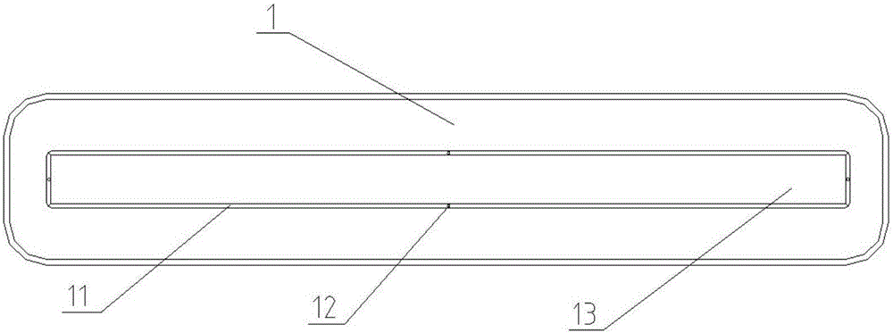
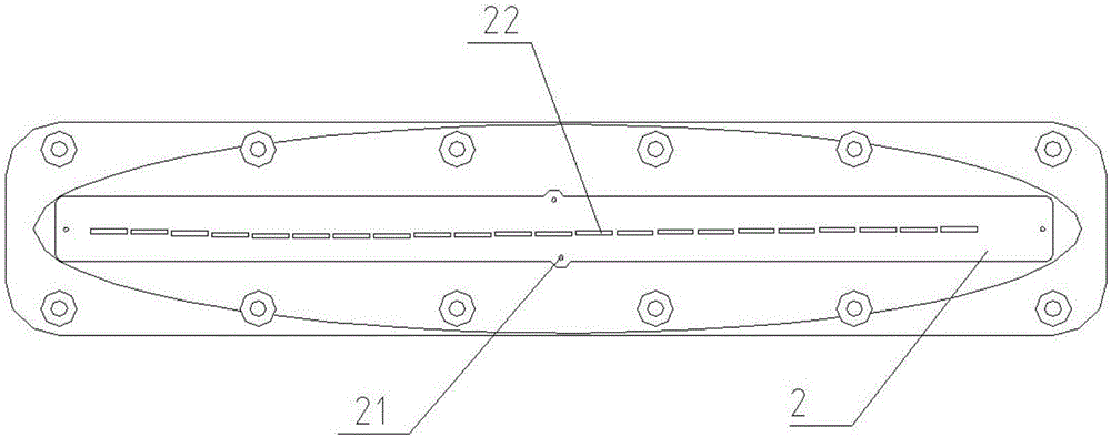
[0033] 2) Assemble the cavity and cover plate of the radiator as required. The structural diagram of cavity 1 and cover plate 2 is as follows figure 1 and figure 2 shown;

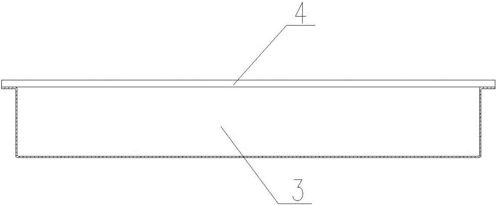
[0034] 3) Design the welding process box and welding tool, put the assembled radiator in the process box, put the welding tool in the vacuum furnace, and then put the process box on the welding tool; the structural diagram of the welding process box and welding tool like image 3 and Figure 4 shown;

[0035] 4) Carry out vacuum brazing to the radiator, the specific steps are as follows:

[0036] ①Raise the temperature from room temperature to 550°C, and the heating rate is 45±5°C / min;

[0037] ②Insul...


PUM


Abstract

The invention provides a vacuum brazing method for a radio fuze antenna radiator. The vacuum brazing method comprises the following steps: 1) preparing a soldering lug by adopting a linear cutting mode; 2) assembling a cavity and a cover plate of the radiator according to requirements; 3) designing a welding process box and a welding tool, putting the assembled radiator into the process box, and then, putting the process box onto the welding tool which is put into a vacuum furnace in advance; 4) carrying out vacuum brazing on the radiator; and 5) carrying out thermal treatment on the brazed radiator. According to the vacuum brazing method, the soldering lug is prepared by adopting the linear cutting mode, so that break-off is avoided, and the time is saved; the soldering lug is fixed by four locating pins on a welding step, and the vacuum welding tool is supplemented, so that the welding defects of uneven welding flux filling, soldering skips and the like are greatly avoided, and the apparent mass is improved; according to the optimized process, a thermal treatment process is independent, thereby shortening the vacuum brazing and cooling time, and greatly improving the vacuum brazing efficiency.

Description

technical field [0001] The invention relates to the technical field of vacuum brazing, in particular to a vacuum brazing method for a radio fuze antenna radiator. Background technique [0002] The radiator is an important component of the radio fuze antenna, which is formed by vacuum brazing of the cavity, the welding piece and the cover plate. The microwave transmission channel is formed by its connection with the cable, and its main function is to receive, transmit and transmit signals. Therefore, the welding quality of the radiator directly affects the electrical performance and parameters, and determines the accuracy of signal transmission. [0003] The original process is: three sets of products are welded in one furnace; the solder tabs are made by hand, because the solder tabs are very brittle, not only the production speed is slow, but also the solder tabs are prone to breakage during the manual production process; during the assembly process The solder tabs made by...

Claims


Application Information

Patent Timeline
IPC IPC(8): B23K1/008B23K1/20
CPCB23K1/0008B23K1/008B23K1/20
Inventor 田叶青
Owner GUIZHOU AEROSPACE ELECTRONICS TECH
Learn More