Cord transmission robot arm drive unit

A technology of transmission machinery and driving devices, applied in the field of mechanical arms, can solve the problems of increasing the resistance of the driving device, achieve the effects of reducing resistance, reducing torque, and improving transmission efficiency

Active Publication Date: 2015-11-18
SHANGHAI JIAO TONG UNIV
View PDF9 Cites 6 Cited by
  • Summary
  • Abstract
  • Description
  • Claims
  • Application Information

AI Technical Summary

Problems solved by technology

Since the outer diameter of the robotic arm used for human surgery is relatively small, it can be seen that the driving wires of the drive system in these two patents are bent very severely after being connected to the robotic arm, which increases the resistance of the driving device

Method used


Image

  • Cord transmission robot arm drive unit
  • Cord transmission robot arm drive unit
  • Cord transmission robot arm drive unit

Examples


Embodiment Construction

[0041] The present invention will be described in detail below in conjunction with specific embodiments. The following examples will help those skilled in the art to further understand the present invention, but do not limit the present invention in any form. It should be noted that those skilled in the art can make several modifications and improvements without departing from the concept of the present invention. These all belong to the protection scope of the present invention.

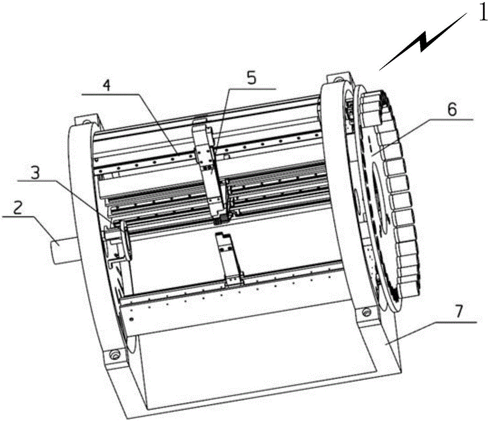
[0042] In this example, if figure 1 As shown, it is a schematic diagram of the overall structure of the driving device of the wire transmission mechanical arm provided by the present invention. In order to clearly express the internal structure, part of the transmission unit is hidden. It can be seen from the figure that its overall structure is cylindrical, while the general wire-driven continuum-shaped manipulator is cylindrical, so that the driving device and the continuum-shaped manipulator c...


PUM


Abstract

The invention provides a cord transmission robot arm drive unit comprising a clamp device, a driving transmission module, a connecting clamp device and a support frame; the driving transmission module is arranged on the support frame; the connecting clamp device is connected with the driving transmission module; the clamp device is connected on an outer side of a front plate of the support frame; the cord transmission robot arm drive unit also comprises a line expander arranged on an inner side of the front plate of the support frame; the line expander is used for guiding a drive cable; the cord transmission robot arm drive unit is provided with the line expander so as to provide a proper room for the driving transmission module, thus improving space utilization rate; the cord transmission robot arm drive unit is compact in structure; the driving transmission module moves outwards in a radial direction so as to reduce a distance between a force bearing point and a transmission unit, thus greatly reducing a moment, and reducing resistance load of the cord transmission robot arm drive unit.

Description

technical field [0001] The invention relates to a mechanical arm, in particular to a driving device for a wire-rope-driven mechanical arm. Background technique [0002] The joints of traditional manipulators are directly driven by motors and other mechanisms. Although the mechanism is simple, it increases the load of the manipulator, and the structure is not compact and the efficiency is low. In order to reduce the self-weight of the multi-stage manipulator in series, to improve its space movement and the ability of the end to carry the load, it is best to separate the manipulator and the driving device. At present, most of the research at home and abroad is the continuum manipulator driven by the wire. Because of its super-redundancy and compliance, this kind of robotic arm has important potential applications in the automation of confined spaces such as nuclear industry and aerospace. [0003] By searching the prior art documents, it is found that Chinese Patent Publicat...

Claims


Application Information

Patent Timeline
Patent Type & Authority Applications(China)
IPC IPC(8): B25J19/00
Inventor 汤磊谷国迎朱向阳朱利民李琳琳王俊刚
Owner SHANGHAI JIAO TONG UNIV
Why Eureka
Try Eureka