A kind of ceramic forming equipment

A technology of molding equipment and ceramics, which is applied to supply devices, pressing rollers, and manufacturing tools, etc., can solve the problems that the mud cannot be mixed with new mud, the wall thickness of ceramics is uneven, and the production cannot be performed normally, so as to reduce production costs. Simple structure and low production cost

Active Publication Date: 2017-06-20
JIAXIAN SHENQIAN LEGEND CERAMICS CHINAWARE FACTORY
View PDF8 Cites 0 Cited by
  • Summary
  • Abstract
  • Description
  • Claims
  • Application Information

AI Technical Summary

Problems solved by technology

[0003] When preparing smaller pottery pieces with a mud mixer, especially for some fine ceramic pieces, there is a very strict standard for the single dosage of mud. Under the background of mass production in modern industry, this will cause very large waste. In order to reduce waste, these mud materials must be processed twice, but these leftover mud materials usually cannot be mixed with new mud materials and must be processed separately Secondary processing, which brings a lot of inconvenience to production, and most of the traditional single-shaft mud refining machines only include a mud refining mechanism and a stirring shaft with a helical blade. There is no very accurate measurement standard when taking mud, and it needs to be completely operated. experience of workers, which will bring a lot of inconvenience to production
[0004] Simultaneously, in the conventional manual ceramic roll forming machine commonly used in the prior art, the upper die seat on the pressure bar is often directly fastened on the pressure bar and cannot be adjusted, which is not practical in actual production. With the continuous use of the press, the position of the rolling head and the rotating shaft will inevitably deviate. Once this happens, it will directly lead to uneven wall thickness of the ceramic and cannot be produced normally.

Method used


Image

  • A kind of ceramic forming equipment
  • A kind of ceramic forming equipment

Examples


Embodiment Construction

[0024] The present invention will be described in detail below in conjunction with accompanying drawing and specific embodiment, and present embodiment is based on the premise of technical scheme of the present invention, has provided detailed implementation and specific operation process, but protection scope of the present invention is not limited to following implementation example.

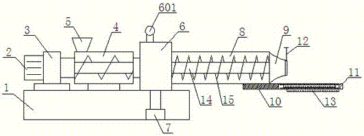
[0025] As shown in the figure, the present invention is a kind of ceramic molding equipment, which includes a mud refining machine and a rolling forming machine. The mud material is extruded from the mud refining machine and then formed by the rolling forming machine. The base 1 is provided with a mud training mechanism and a stirring shaft 14, and the mud training mechanism includes a feeding mixing drum 4, a vacuum box 6 and a mud training discharging drum 8 connected successively from front to back, wherein the feeding mixing drum 4 and The mud-practicing discharge cylinder 8 is a cylindric...


PUM


Abstract

Ceramic forming equipment comprises a pug mill and a rolling molding machine, wherein a clay material is extruded by the pug mill and then molded by the rolling molding machine, a cutting plate is arranged on the end surface of a discharging opening in the pug mill in a sliding manner, a guide plate is fixedly arranged below the discharging opening, a graduation ruler is horizontally arranged on the guide plate, and the beginning graduation position of the graduation ruler is flush with the end surface of the discharging opening; and in the rolling molding machine, an upper die holder is arranged on a presser bar, a sliding groove is formed in the presser bar, the upper die holder is arranged in the sliding groove in a sliding manner, a return plate is horizontally fixedly arranged at the end part of the lower end of the presser bar, the return plate is connected with one side wall of a rack through a return spring, and a V-shaped structure is formed through connecting the return plate with the presser bar. The ceramic forming equipment has the advantages that the guide plate with the horizontal graduation ruler is arranged in the discharging opening of the pug mill, so that the use efficiency of the clay material is improved; in the rolling molding machine, the upper die holder is arranged in the sliding groove in a sliding manner, so that the thickness of a ceramic-formed wall can be regulated; and through the combination use of the pug mill and the rolling molding machine, the ceramic forming efficiency is further improved.

Description

technical field [0001] The invention relates to the field of ceramic molding, in particular to a ceramic molding equipment. Background technique [0002] Ceramic molding is one of the important processes in ceramic manufacturing. The commonly used molding techniques include dry pressing, plastic molding, grouting and isostatic pressing, among which the most commonly used molding methods are dry pressing or semi-dry pressing. The so-called dry pressing molding is to prepare the ceramic powder into powder with good fluidity and suitable granulation through plasticization and granulation, put it into the mold, and apply external pressure through the plunger of the rolling forming machine, so that The powder is pressed into a green body of a certain shape. Among them, the ceramic powder needs to be evenly stirred by a mud mixer to extrude the mud with strong plasticity, and then formed by a rolling forming machine. [0003] When preparing smaller pottery pieces by the clay ref...

Claims


Application Information

Patent Timeline
Patent Type & Authority Patents(China)
IPC IPC(8): B28B3/12B28B13/02B28C1/16B28C1/22
CPCB28B3/12B28B13/0235B28C1/16B28C1/225
Inventor 李俊锋
Owner JIAXIAN SHENQIAN LEGEND CERAMICS CHINAWARE FACTORY
Why Eureka
Try Eureka