Gas multi-stage liquefying plant driven by acoustic resonance type thermo-acoustic engine

A thermoacoustic engine and acoustic resonance technology, which is applied in refrigeration and liquefaction, gas cycle refrigerators, refrigerators, etc., can solve problems such as the inability to realize the overall process of gas liquefaction, and achieve compact structure, good application prospects, and high energy density. Effect

Active Publication Date: 2015-11-18
TECHNICAL INST OF PHYSICS & CHEMISTRY - CHINESE ACAD OF SCI
View PDF7 Cites 4 Cited by
  • Summary
  • Abstract
  • Description
  • Claims
  • Application Information

AI Technical Summary

Problems solved by technology

[0005] The purpose of the present invention is to provide a gas multi-stage liquefaction device driven by an acoustic resonance type thermoacoustic engine in order to overcome the overall process problem that the above system cannot realize gas liquefaction. The system has a simple and compact structure, no moving parts, and is safe and reliable. The thermoacoustic engine unit works in the traveling wave phase, has high energy density, can lower the gas temperature step by step, and has small heat transfer loss; it has broad development and application prospects in gas liquefaction

Method used


Image

  • Gas multi-stage liquefying plant driven by acoustic resonance type thermo-acoustic engine
  • Gas multi-stage liquefying plant driven by acoustic resonance type thermo-acoustic engine
  • Gas multi-stage liquefying plant driven by acoustic resonance type thermo-acoustic engine

Examples


Embodiment 1

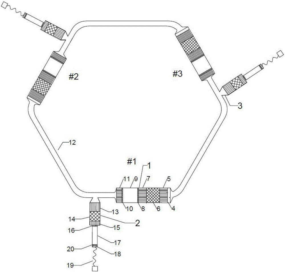
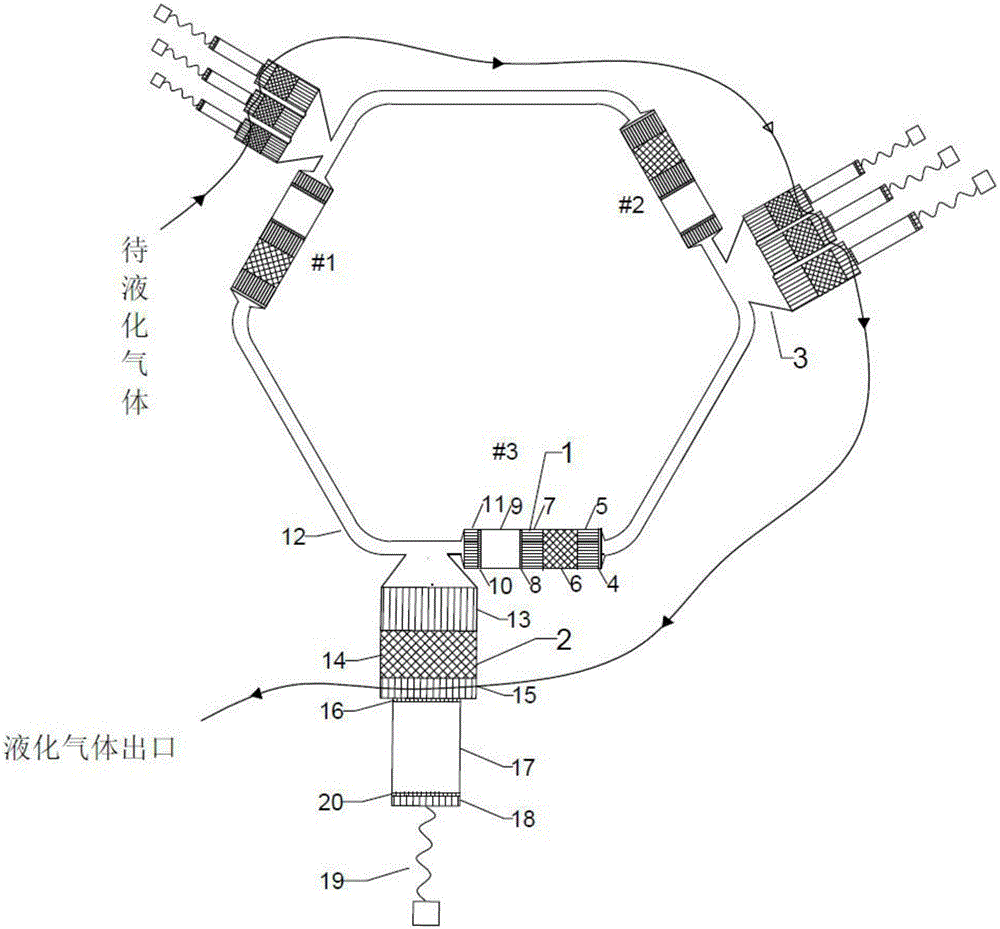
[0024] figure 2 It is a structural schematic diagram of an acoustic resonance thermoacoustic engine-driven gas multistage liquefaction device (Example 1) of the present invention. Such as figure 2 As shown, the gas multistage liquefaction device driven by acoustic resonance type thermoacoustic engine in Example 1 has 3 stages (#1 thermoacoustic engine unit, #2 thermoacoustic engine unit and #3 thermoacoustic engine unit) with heat equal in length. The acoustic engine unit 1 and the third-stage bypass 3; the thermoacoustic engine units at all levels are connected end-to-end through the resonant tube 12 to form a loop structure; each bypass 3 is connected to the pulse tube refrigerator unit 2, wherein the first stage and the first stage The second-stage bypasses are respectively connected (parallel) to three pulse tube refrigerator units 2, and the third-stage bypass is connected to one pulse-tube refrigerator unit 2, and the size (length and cross-sectional area) of each ref...

Embodiment 2

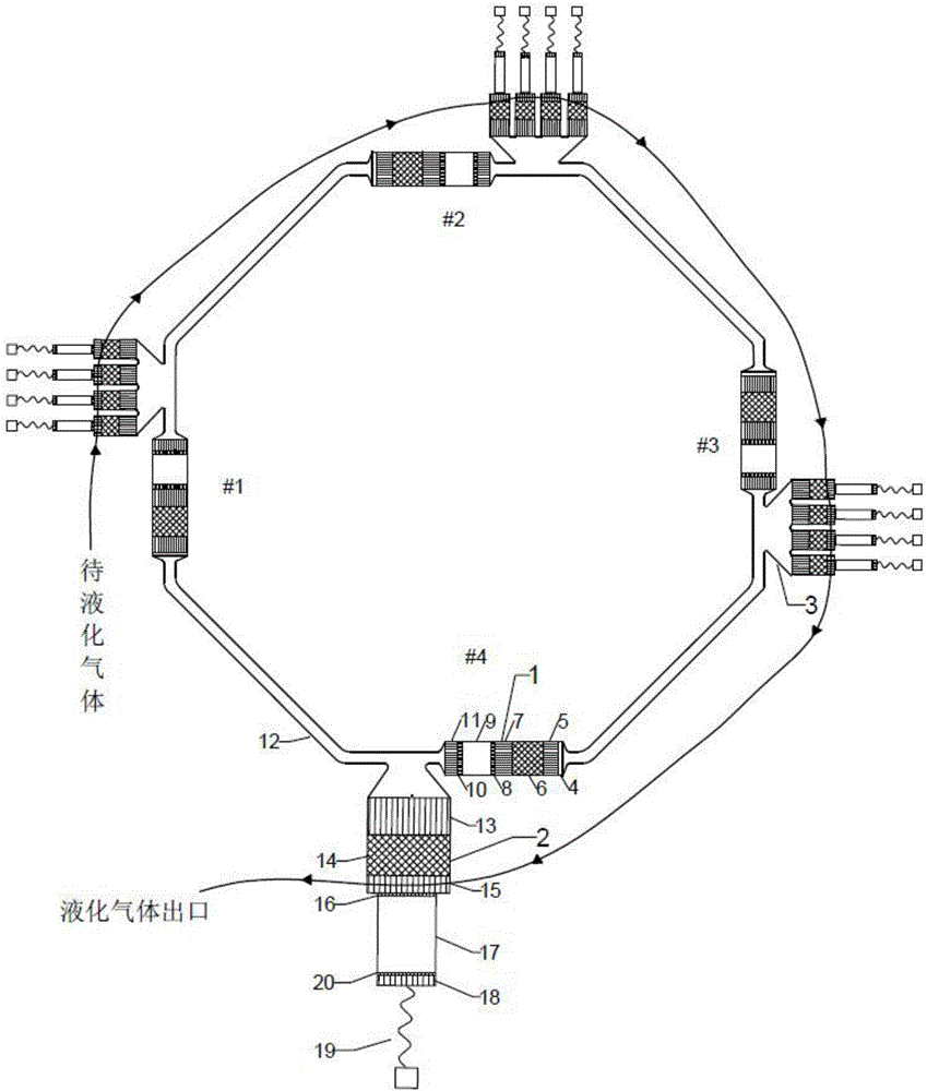
[0029] image 3 It is a structural schematic diagram of the gas multistage liquefaction device (embodiment 2) driven by an acoustic resonance type thermoacoustic engine of the present invention; image 3 As shown, the gas multistage liquefaction device of the present embodiment 2 has 4 stages (#1 thermoacoustic engine unit, #2 thermoacoustic engine unit, #3 thermoacoustic engine unit and #4 thermoacoustic engine unit) with equal dimensions (length and cross-sectional area) thermoacoustic engine unit and 4 bypasses; the thermoacoustic engine units at all levels are connected end-to-end through resonant tubes 12 of the same size to form a loop structure; each bypass 3 is connected to a pulse tube refrigerator unit 2 , wherein, except that the bypass connected to the #4 (4th stage) thermoacoustic engine unit is connected with a pulse tube refrigerator unit, the other bypasses are connected (parallel) with 4 pulse tube refrigerator units; and the size of each refrigerator unit (l...


PUM


Abstract

The invention provides a gas multi-stage liquefying plant driven by an acoustic resonance type thermo-acoustic engine. The gas multi-stage liquefying plant is compedos of N stages of thermo-acoustic engine units of a loop structure and N stages of bypasses, wherein the loop structure is formed by connecting resonant tubes end to end; the N stages of bypasses are arranged in engine secondary water cooler outlets; the Nth-stage bypass is connected with a pulse tube refrigerator unit, and the rest bypasses are connected with at least three pulse tube refrigerator units; in the working process, engine heaters are heated, a system generates reciprocating oscillation pressure fluctuation and generates thermo-acoustic conversion in refrigerator heat regenerators, cold end heat is sent to refrigerator main coolers, and cold ends are kept at low temperatures; along with increase of the number of the stages of the bypasses, the temperatures of the cold ends are gradually reduced to the gas liquefaction temperature; gas sequentially flows through the cold ends of the first-stage bypass to the (N-1)th-stage bypass according to the cold end temperatures from high to low, sensible heat is released, and the temperatures are reduced to the liquefaction temperature; and the gas finally passes the cold end of the Nth-stage bypass to be transformed in a liquid state from a gas state. The temperature of the gas can be reduced in a gradient manner and heat transfer losses are reduced; and no mechanical moving part exists, the structure is compact, and the whole process of gas liquefaction can be achieved.

Description

technical field [0001] The invention belongs to the field of gas liquefaction, and in particular relates to a gas multistage liquefaction device driven by an acoustic resonance type thermoacoustic engine. Background technique [0002] Liquefaction is the process of changing a substance from a gaseous state to a liquid state. Since the volume of gas after liquefaction usually becomes one thousandth of its original volume, which is convenient for storage and transportation, some gases are usually liquefied in reality. There are two ways to achieve liquefaction, one is to lower the temperature, and the other is to compress the volume. Any gas can be liquefied when the temperature drops low enough. [0003] A thermoacoustic engine is a device that uses pipes and heat exchangers to obtain a suitable sound field inside it, and converts external heat energy into sound energy through the interaction between the working medium and the solid packing of the regenerator, with no mecha...

Claims


Application Information

Patent Timeline
Patent Type & Authority Applications(China)
IPC IPC(8): F25B9/14
CPCF25B9/145F25B2309/1403
Inventor 罗二仓徐静远胡剑英戴巍吴张华张丽敏余国瑶王晓涛陈燕燕
Owner TECHNICAL INST OF PHYSICS & CHEMISTRY - CHINESE ACAD OF SCI
Why Eureka
Try Eureka