
An evaporation tube with a slit-shaped steam outlet

A technology of discharge port and evaporating tube, applied in the field of evaporating tube, can solve the problems of inapplicability of low-pressure refrigerant, reduction of the number of steam bubbles, reduction of the frequency of debodying of steam bubbles, etc., so as to improve the effect of boiling heat transfer and increase the heat transfer of boiling. The effect of coefficients

Active Publication Date: 2017-03-08
山东恒辉节能技术集团有限公司
View PDF2 Cites 0 Cited by
  • Summary
  • Abstract
  • Description
  • Claims
  • Application Information

AI Technical Summary

Problems solved by technology

[0007] The widely used T-shaped finned and cavity-structured evaporating tubes and the improved evaporating tube structure play a very good role in evaporating refrigerants with high working pressure, such as R134a, whose boiling pressure reaches about 0.3MPa. However, when it is used as a low-pressure boiling working fluid, such as R245fa, its boiling pressure is lower than one atmospheric pressure, and its physical properties are quite different from R134a, such as viscosity, surface tension, vapor density, etc., all change, which is obvious in the experiment. The number of steam bubbles is greatly reduced, the volume of the bubbles becomes larger, and the frequency of bubble separation decreases, which affects the boiling heat transfer coefficient, and the effect is not satisfactory.
Experiments show that the conventional tube type can be suitable for refrigerant R134a, but not suitable for low-pressure refrigerants, such as R245fa

Method used


Image

  • An evaporation tube with a slit-shaped steam outlet
  • An evaporation tube with a slit-shaped steam outlet
  • An evaporation tube with a slit-shaped steam outlet

Examples


Embodiment

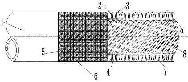
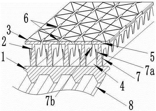
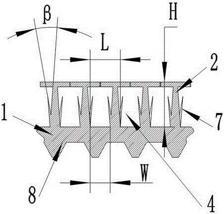
[0027] Embodiment: a kind of evaporating tube with slit-shaped steam outlet (see Figure 1-Figure 5 ), which includes a tube body 1, the outer surface of the tube body 1 is provided with T-shaped fins, the T-shaped fins are composed of fins 2 and platforms 3 extending from the top of the fins 2 to both sides, and the outer surface of the T-shaped fins is provided with Extend triangular micro-grooves 5 in various directions, including triangular micro-grooves extending in the axial and radial directions and at angles of 45° and 135° to the axis, and the intersection points of the grooves extending in various directions form a "m" shape , the intersection point is the steam discharge port 6 generated in the cavity, and the shape of the steam discharge port 6 is a narrow slit; the side of the fin 2 is provided with a triangular protrusion 7, and each side of the triangular protrusion 7 is straight and faces the fin. The surface of the protrusion on the side wall of sheet 2 is pla...


PUM

PropertyMeasurementUnit
Heightaaaaaaaaaa
Widthaaaaaaaaaa
Helix angle αaaaaaaaaaa

Abstract

The invention discloses an evaporating pipe with a narrow-gap steam exhaust opening. T-shaped fins are arranged on the outer surface of the evaporating pipe; a hole is formed between the adjacent fins; spiral channels are formed in the inner surface of a heat transfer pipe. The evaporating pipe is characterized in that a plurality of grooves which extend along the axial direction, the radial direction and the directions which form different included angle together with the axial direction are formed in the outer surface; the intersection of the grooves which extend in different directions is in a shape like a Chinese character 'mi'; a channel which is communicated with the holes outside the pipe is formed in the intersection, i.e., an exhaust opening for steam in the holes is formed; the exhaust opening is in a narrow-gap shape; meanwhile, triangular bulges are formed in the side surfaces of the T-shaped fins, and are protruded on the side surfaces, which are close to the fins as much as possible; the included angles of the triangular bulges and the surfaces of the fins are acute angles. The evaporating pipe with the narrow-gap steam exhaust opening disclosed by the invention works with a low-pressure refrigerant medium, evaporation cores are easy to nucleate and large in number; the bubble detachment frequency is high; the heat exchange effect is good.

Description

[0001] Technical field: [0002] The invention discloses an evaporation tube with a slit-shaped steam discharge port, which belongs to a high-efficiency heat exchange tube in a flooded evaporator in a refrigeration and air-conditioning system, and is especially suitable for a low-pressure refrigerant, such as R245fa, as a working medium evaporator . [0003] Background technique: [0004] Flooded evaporators are an indispensable and important component in commercial refrigeration systems. The performance of the evaporator depends largely on the heat exchange performance of the heat transfer copper tube in the evaporator. In a flooded evaporator, the refrigerant submerges the heat exchange tubes in the evaporator. When the hot fluid flows through the tubes, heat is transferred from the hot fluid to the refrigerant outside the tubes, causing the refrigerant to boil to produce steam. An important way to improve the heat transfer efficiency of the evaporator is to enhance the boi...

Claims


Application Information

Patent Timeline
IPC IPC(8): F28F1/12F25B39/02
Inventor 李小利马青川王斌王春生孟昱言王申英宋辉
Owner 山东恒辉节能技术集团有限公司
Learn More