Check patentability & draft patents in minutes with Patsnap Eureka AI!

Method for calibrating surface-mounted fiber grating strain sensor

A technology of strain sensor and optical fiber grating, which is applied in the direction of instruments, optical devices, measuring devices, etc., can solve the problem that the influence of the strain sensitivity of the strain optical fiber grating strain sensor is not considered, and the measured value of the optical fiber grating deviates from the true strain value of the object under test , deviation of actual strain measurement results and other issues, to achieve the effect of accuracy guarantee, temperature stability, and small temperature fluctuation interference

Active Publication Date: 2015-11-18
山东双测安全信息技术产业研究院有限公司
View PDF12 Cites 23 Cited by
  • Summary
  • Abstract
  • Description
  • Claims
  • Application Information

AI Technical Summary

Problems solved by technology

In the actual application process, the sensitivity of the surface-mounted optical fiber grating strain sensor to strain will vary due to the difference in the strain transfer rate caused by the different substrate materials and adhesives, which will cause the measured value of the optical fiber grating to deviate from the true strain value of the test piece.
[0003] At present, the calibration method of the surface-mounted FBG strain sensor does not consider the influence of the substrate material and adhesive on the strain sensitivity of the FBG strain sensor during the actual strain measurement process, resulting in deviations in the actual strain measurement results.

Method used


Image

  • Method for calibrating surface-mounted fiber grating strain sensor
  • Method for calibrating surface-mounted fiber grating strain sensor

Examples


Embodiment Construction

[0022] Specific embodiments of the present invention will be described below in conjunction with the accompanying drawings, so as to better understand the present invention.

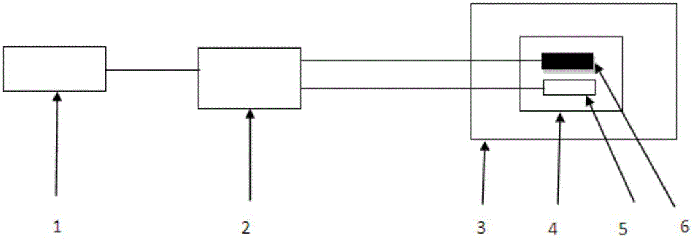
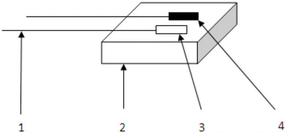
[0023] The calibration method of the surface-mounted optical fiber grating strain sensor of the present invention utilizes the finite element analysis of the strain generated by thermal expansion and contraction of materials to realize the calibration of the sensitivity coefficient of the optical fiber grating strain sensor. Such as figure 1 As shown, the calibration system of the fiber grating strain sensor calibration method of the present invention includes a computer 1, a fiber grating demodulator 2, a constant temperature bath 3, a standard part 4, a fiber grating temperature sensor 5, and a fiber grating strain sensor 6. Such as figure 2 As shown, the FBG strain sensor is pasted on the standard part along the horizontal direction, and the FBG temperature sensor is arranged near the FBG strain sen...


PUM


Abstract

The invention provides a method for calibrating a surface-mounted fiber grating strain sensor. A standard member of a same material with an object, of which the strain is measured, is selected, a certain surface treatment is carried on the central position of the upper surface of the standard member, and the fiber grating strain sensor is pasted along the horizontal direction. A fiber grating temperature sensor is arranged beside the fiber grating strain sensor, and suspended under an unstrained state. After standing for 48 hours, the standard member with the fiber grating sensor arranged is placed in a constant temperature tank. The fiber grating sensor is connected to a fiber grating demodulation instrument to record the wavelength change of a sensor. The temperature of the constant temperature tank is adjusted, and the standard member is deformed due to expending with heat and contracting with cold and changes the bearing state of fiber gratings. The surface strain of the standard member can be obtained based on finite element analysis, and calibrating strain sensitivity coefficient of the fiber grating strain sensor can be realized through certain calculation. The method minimizes the influence of strain transmissibility change due to pasting substrate material and adhesives, and the reliability of the strain sensitivity coefficient is improved.

Description

technical field [0001] The invention belongs to the technical field of optical fiber grating measurement, and in particular relates to a calibration method for a surface-mounted optical fiber grating strain sensor. Background technique [0002] With the development of fiber grating sensing technology, fiber grating sensor has many unique advantages, such as small size, light weight, anti-electromagnetic interference, and easy large-scale networking to realize real-time distributed measurement, etc., gradually replacing traditional electrical sensors. Sensors are widely used in structural health monitoring. At present, fiber gratings have been successfully applied in aerospace, ocean platforms, civil bridges, and long-span space structures. In the actual application process, the sensitivity of the surface-mounted fiber optic grating strain sensor to strain will vary due to the difference in strain transfer rate caused by the difference in the substrate material and adhesive,...

Claims


Application Information

Patent Timeline
IPC IPC(8): G01B11/16
Inventor 魏鹏刘旭建李成贵
Owner 山东双测安全信息技术产业研究院有限公司
Features
  • R&D
  • Intellectual Property
  • Life Sciences
  • Materials
  • Tech Scout
  • Unparalleled Data Quality
  • Higher Quality Content
  • 60% Fewer Hallucinations
Learn More