Excitation light source circuit for direct-reading spectrometer

A technology of direct reading spectrometer and power supply circuit, applied in the direction of electrical excitation analysis, material excitation analysis, etc., can solve problems such as interference safety, impact on equipment miniaturization, hidden dangers, etc., and achieve high reliability, smaller size, and reduced energy difference. Effect

Inactive Publication Date: 2015-11-18
无锡创想分析仪器有限公司
View PDF5 Cites 0 Cited by
  • Summary
  • Abstract
  • Description
  • Claims
  • Application Information

AI Technical Summary

Problems solved by technology

[0006] 1. The main power circuit of the excitation light source mostly uses a combination of inductors and capacitors to form different L and C ratios, thereby forming the required discharge current during the discharge process of the sample to be analyzed. The bulky inductors and capacitors affect the miniaturization of the equipment, and The discreteness of inductance and capacitance makes the energy of different excitation light sources very different;
[0007] 2. In order to form an effective discharge circuit between the sample to be analyzed and the excitation electrode, a high voltage of about 10,000 volts is required to ignite the circuit, which will bring strong interference and potential safety hazards, and affect the reliability of the equipment

Method used


Image

  • Excitation light source circuit for direct-reading spectrometer
  • Excitation light source circuit for direct-reading spectrometer
  • Excitation light source circuit for direct-reading spectrometer

Examples


Embodiment Construction

[0021] The embodiments listed in the present invention are only used to help understand the present invention, and should not be interpreted as limiting the protection scope of the present invention. For those of ordinary skill in the art, they can also Improvements and modifications are made to the present invention, and these improvements and modifications also fall within the protection scope of the claims of the present invention.

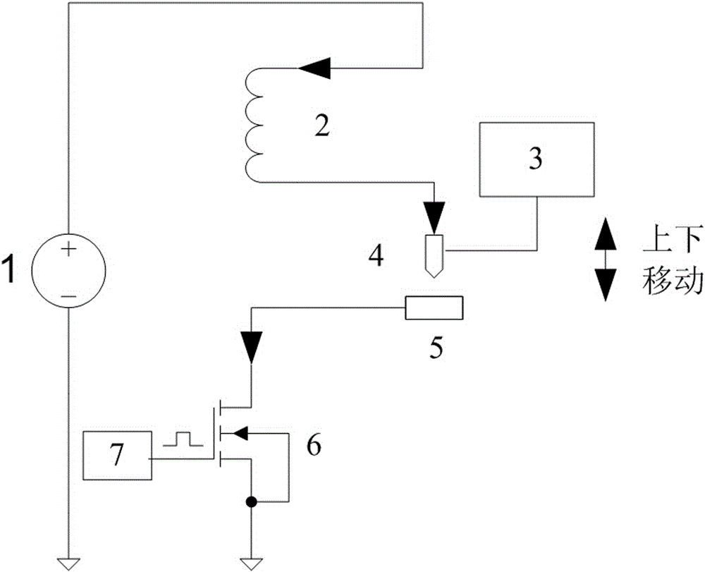
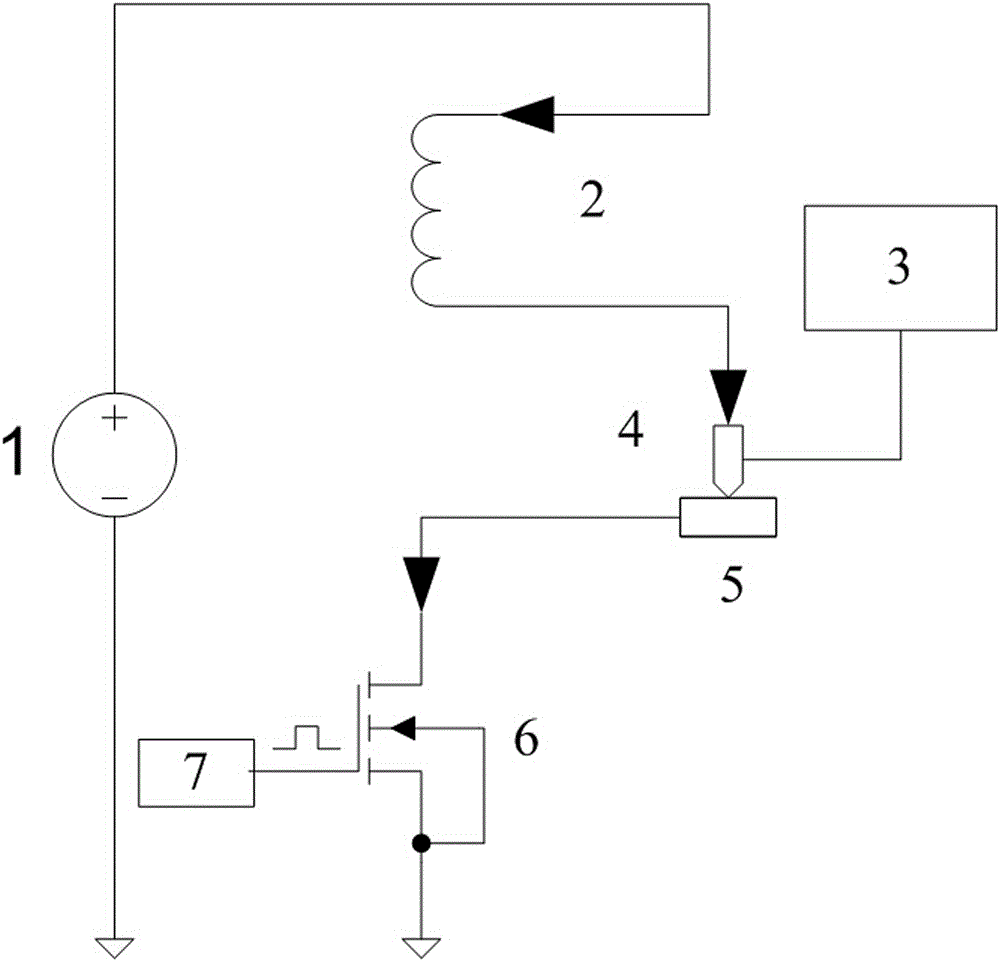
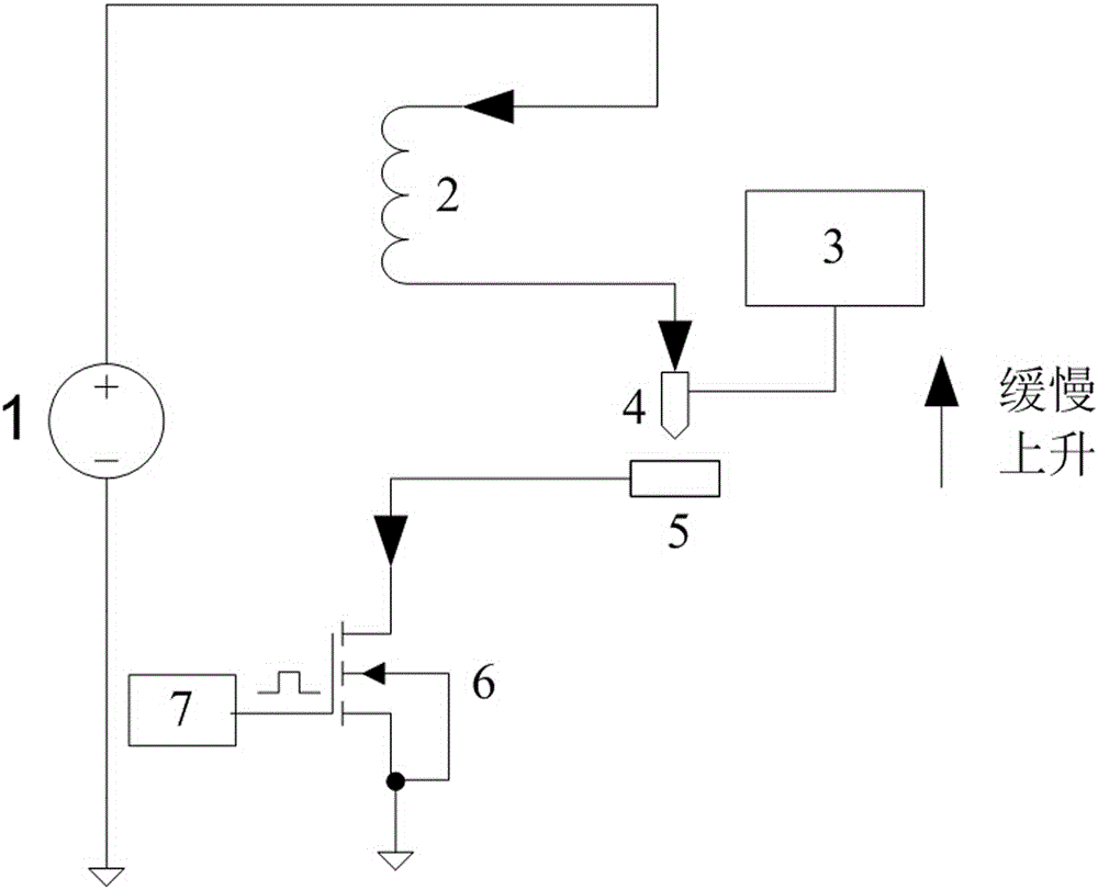
[0022] Such as figure 1 As shown, a direct-reading spectrometer excitation power circuit of the present invention, the excitation power circuit instantly heats the atoms in the sample 5 to be analyzed to form an atomic emission spectrum, and the excitation light source circuit includes a DC power supply 1, a power inductor 2, a stepping motor 3, The excitation electrode 4, the power MOS tube 6 and the power MOS tube drive circuit 7, the DC power supply 1 provides DC current to the excitation light source circuit, the power inductor 2 blocks the...


PUM


Abstract

The invention relates to an excitation light source circuit for a direct-reading spectrometer. The excitation light source circuit comprises a direct current supply for supplying direct current to the excitation light source circuit, a power inductor for blocking alternate current to realize the fact that only direct current exists in the excitation light source circuit, a stepping motor for controlling an exciting electrode to move up and down, the exciting electrode discharging at the pointed end to generate electric arc to realize stable arc discharge with a sample to be analyzed to further enable atoms in the sample to be analyzed to shine, a power MOS transistor for controlling the formation and disconnection of a discharge loop, and a power MOS transistor drive circuit for controlling impulse to control the power MOS transistor to be conductive and non-conductive. According to the invention, high-voltage ignition is not required, so that interference and potential safety hazard are avoided; the fact that inductors and capacitors are combined to form discharge current is not required, and the intensity and discharge time of the discharge current can be effectively controlled; as the capacitors with huge volume are eliminated, the size of excitation light sources is reduced, and the energy difference among different excitation light sources, caused by the discreteness of capacitors is reduced.

Description

technical field [0001] The invention relates to an excitation light source circuit, in particular to an excitation light source for a direct reading spectrometer. Background technique [0002] The direct-reading spectrometer is a precision optical instrument, its optical structure is placed inside a sealed optical chamber. During the use of the instrument, the optical signal generated by the sample to be analyzed enters the optical chamber and is projected to the line array sensor through the optical structure and converted into The electrical signal is then converted into a digital signal by the electronic module and stored in the single-chip microcomputer. The analysis software running on the computer reads the digital signal from the single-chip microcomputer, analyzes and calculates, and obtains the content of each chemical element in the sample. [0003] Direct reading spectrometer has the advantages of fast analysis speed and high accuracy. Therefore, it is widely used...

Claims


Application Information

Patent Timeline
Patent Type & Authority Applications(China)
IPC IPC(8): G01N21/67
Inventor 马建州廖波袁海军顾惠惠
Owner 无锡创想分析仪器有限公司
Why Eureka
Try Eureka