WLAN channel allocation method based on artificial bee colony algorithm

An artificial bee colony algorithm and channel allocation technology, applied in wireless communication, electrical components, etc.

Active Publication Date: 2015-11-18
合肥庐阳科技创新集团有限公司
View PDF2 Cites 5 Cited by
  • Summary
  • Abstract
  • Description
  • Claims
  • Application Information

AI Technical Summary

Problems solved by technology

However, it is seldom considered how to improve the network throughput of WLAN from the MAC layer of WLAN usi...

Method used


Image

  • WLAN channel allocation method based on artificial bee colony algorithm
  • WLAN channel allocation method based on artificial bee colony algorithm
  • WLAN channel allocation method based on artificial bee colony algorithm

Examples


Embodiment Construction

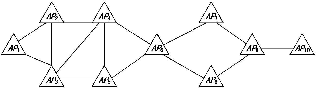
[0079] In this example, if figure 2 As shown, a WLAN channel allocation method based on the artificial bee colony algorithm is applied to N access points AP={AP 1 ,AP 2 ,...,AP i ,...,AP N} and a WLAN network composed of a control center AC; and proceed as follows:

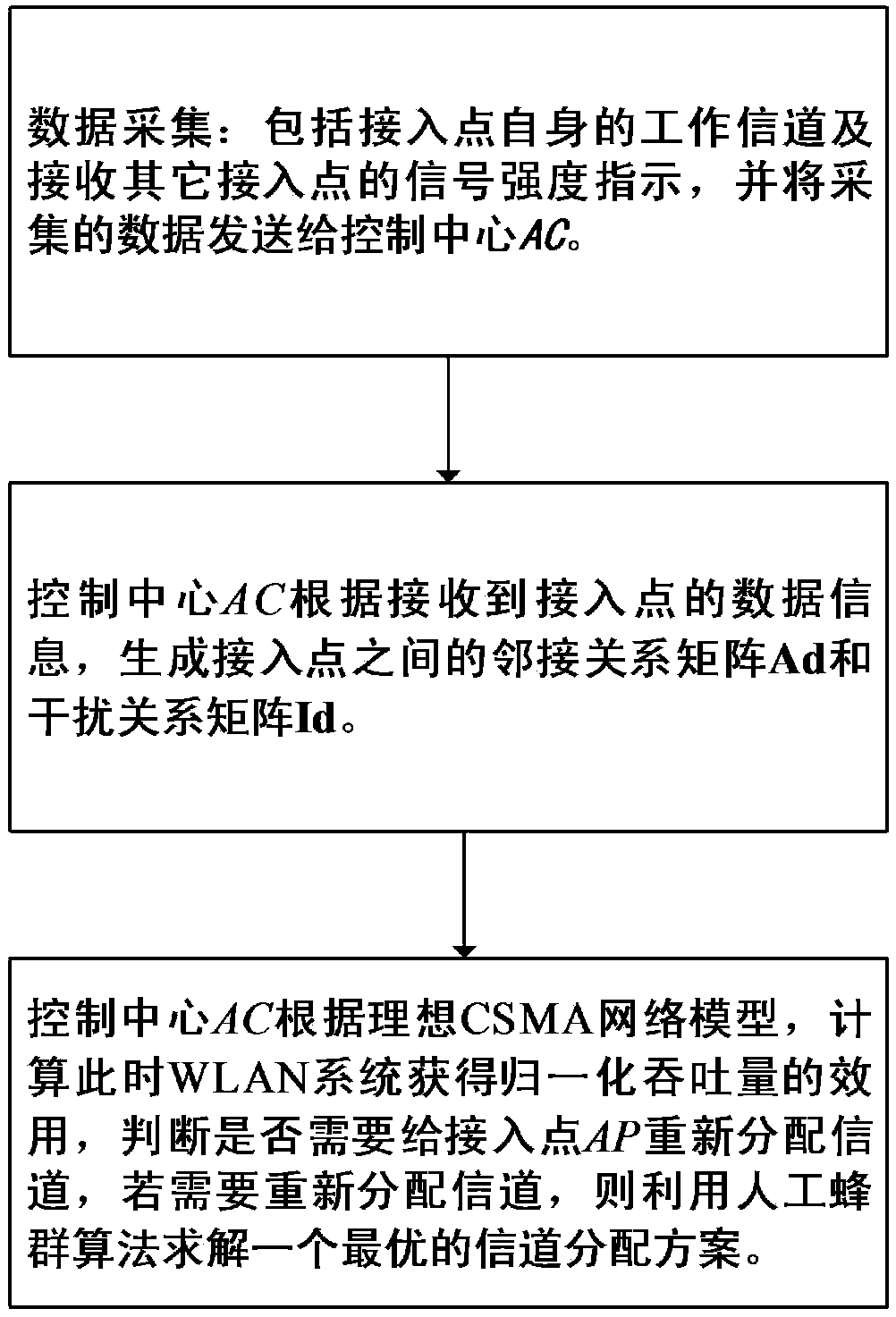
[0080] Step 1. Data collection:

[0081] N access points AP collect their own working channels to form a channel set f={f 1 ,f 2 ,..., f i ,..., f N} and received signal strength indicators of other access points to form a signal strength indicator set R={R 1 , R 2 ,...,R i ,...,R N}, and sent to the control center AC; f i Indicates the i-th access point AP i Own working channel; R i Indicates the i-th access point AP i Received signal strength indications for other access points scanned; and Indicates the i-th access point AP i The jth access point AP among other scanned access points j received signal strength indicator; m i Indicates the i-th access point AP i The number of other access ...


PUM


Abstract

The present invention discloses a WLAN channel allocation method based on an artificial bee colony algorithm. The method comprises the steps of (1) data acquisition, (2) the establishment of a neighborhood relation matrix and an interference relation matrix, (3) channel allocation determination, (4) the channel allocation based on the artificial bee colony algorithm. According to the method, different channels can be distributed to an access point which generates interference, and thus the throughput of a whole network system and the overall performance of the system are improved.

Description

technical field [0001] The invention relates to the technical field of wireless communication, more specifically, a WLAN channel allocation method based on an artificial bee colony algorithm. Background technique [0002] In the field of wireless communication, with the development of wireless technology and the popularization of wireless terminal equipment, WLAN based on the IEEE802.11 standard is becoming more and more popular. Usually, in order to increase the communication coverage area of ​​the WLAN, a large number of APs need to be deployed. However, regardless of the 2.4G frequency band or the 5G frequency band, the available orthogonal channels are often limited. In a densely deployed AP environment, it is inevitable that many APs work on the same channel. APs working on the same channel will generate interference during data transmission, which affects the throughput of the entire WLAN system and degrades the performance of the WLAN system. At present, many channe...

Claims


Application Information

Patent Timeline
IPC IPC(8): H04W72/04H04W72/08H04W74/08
CPCH04W72/04H04W74/0816H04W72/541H04W72/542
Inventor 开彩红肖瑶彭敏
Owner 合肥庐阳科技创新集团有限公司
Why Eureka
Try Eureka