Multi-station vertical engraving and milling machine

A multi-station, engraving and milling machine technology, applied in metal processing machinery parts, manufacturing tools, metal processing equipment and other directions, can solve the problems of large horizontal span, reduce equipment market competitiveness, increase production and transportation costs, etc., to avoid The effect of excess weight

Active Publication Date: 2017-11-07
陈美青
View PDF2 Cites 0 Cited by
  • Summary
  • Abstract
  • Description
  • Claims
  • Application Information

AI Technical Summary

Problems solved by technology

However, the engraving and milling machine proposed by the applicant has eight cutting main motors, and the horizontal span is relatively large. If the front chip flute (authorized announcement number CN203357133U) structure of the CNC machine tool is adopted, the weight of the machine tool will exceed the load capacity of the general loading machine, that is, Will significantly increase production and transportation costs and reduce equipment market competitiveness

Method used


Image

  • Multi-station vertical engraving and milling machine
  • Multi-station vertical engraving and milling machine
  • Multi-station vertical engraving and milling machine

Examples


Embodiment 2

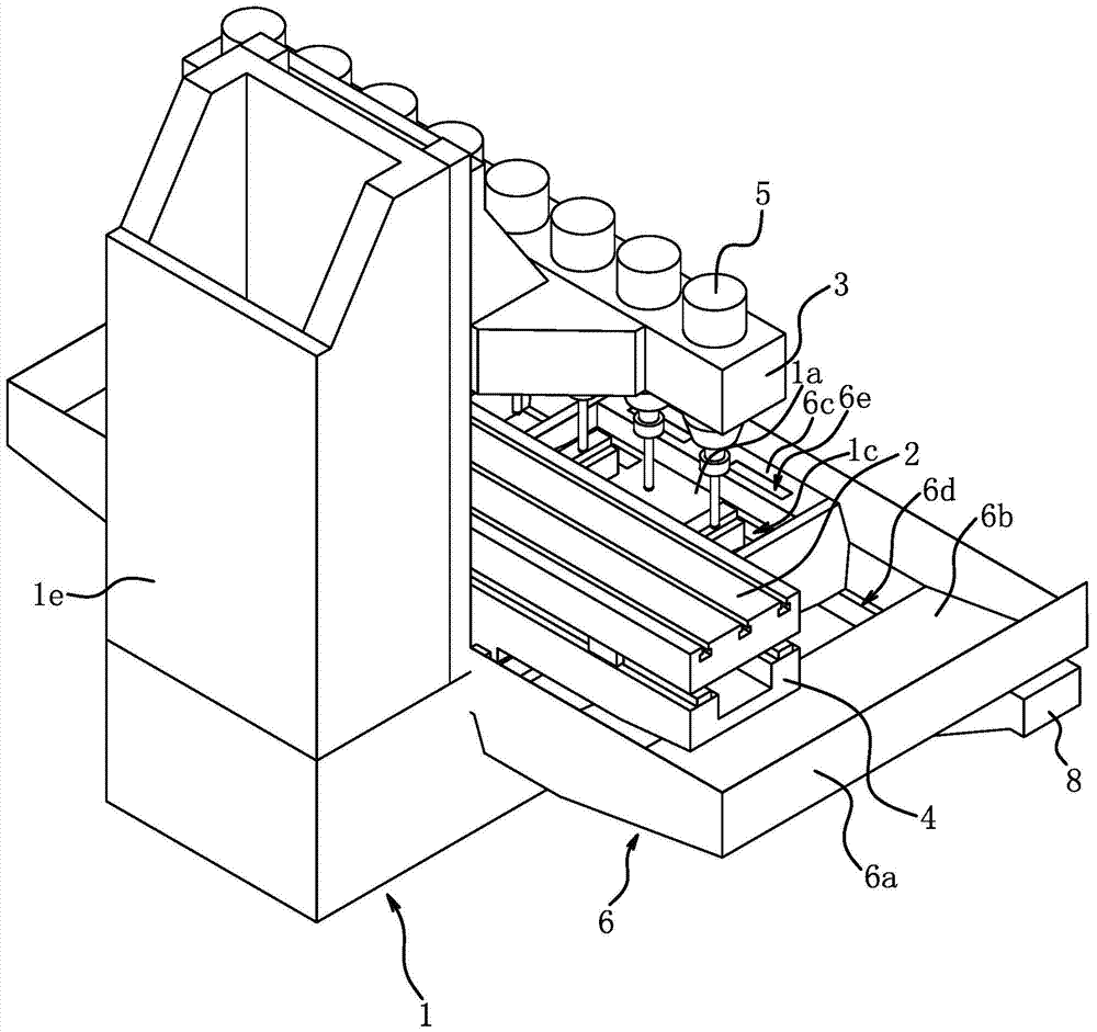
[0032] The structure and principle of this embodiment are basically the same as that of Embodiment 1, and the basic similarities will not be redundantly described, and only the differences will be described, and the differences are as follows: Figure 5 As shown, the number of chip dropping holes 1c is eight, the cross section of the chip dropping holes 1c is trapezoidal, and the cross section of the spacer 1f between the two chip dropping holes 1c is triangular in shape, and the cutting chips in this area fall naturally, further facilitating the base 1 Cleaning of cutting chips.

Embodiment 3

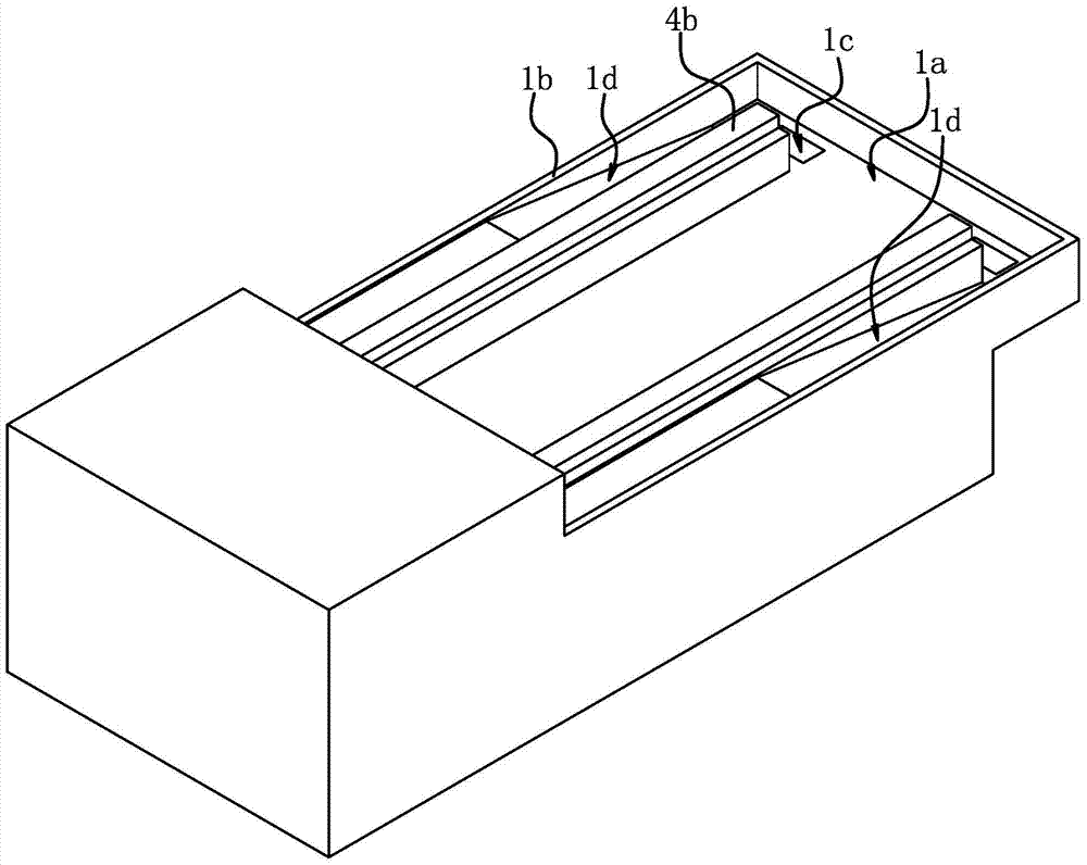
[0034] The structure and principle of this embodiment are basically the same as that of Embodiment 1, and the basic similarities will not be redundantly described, and only the differences will be described, and the differences are as follows: Figure 6 As shown, there are eight chip holes 1c, and the top of the cross section of the spacer 1f between the two chip holes 1c is arc-shaped, so that the cutting chips in this area fall naturally, which further facilitates the cleaning of the cutting chips on the base 1 .

Embodiment 4

[0036]The structure and principle of this embodiment are basically the same as that of Embodiment 1, and the basic similarities will not be redundantly described, and only the differences will be described, and the differences are as follows: Figure 12 The chip conveying device shown is a screw conveyor 9 , and the chip drop hole 1 c , the chip drop hole 1 c and the auxiliary chip drop hole 6 e of the two chip guide buckets 6 b are all in communication with the pipe sleeve of the screw conveyor 9 . The use of the screw conveyor 9 to convey cutting chips can significantly reduce the noise outside the multi-station vertical engraving and milling machine.


PUM


Abstract

The invention provides a multi-station vertical engraving and milling machine and belongs to the technical field of operation. The multi-station vertical engraving and milling machine solves the problem that copper scraps in an existing engraving and milling machine are accumulated on a workbench and cannot be easily cleaned away. The multi-station vertical engraving and milling machine comprises a base, a workbench, a lifting base, a machine hood and a plurality of cutting motors. The workbench is connected with the base through a cross pulling plate with a transverse pulling plate and a longitudinal pulling plate. The front end of the base is provided with a cornice part protruding out of the front side. The outer edge of the base is provided with a strip-shaped water blocking part. The cornice part is provided with a scrap falling hole. The machine hood is provided scrap guiding funnel parts which are located below the two ends of the transverse plugging plate and each in the shape of a funnel, and the scrap guiding funnel parts of the machine hood are fixed to the top face of the water blocking part. According to the multi-station vertical engraving and milling machine, the scrap guiding funnel parts of the machine hood are arranged on the two sides to collect cutting bits, the machine hood is a sheet metal part and small in weight, and therefore the situation that the weight of the engraving and milling machine is too large is effectively avoided, and the engraving and milling machine is suitable for being disassembled and assembled through a common loading machine.

Description

technical field [0001] The invention belongs to the technical field of operations, and relates to an engraving and milling machine, in particular to a multi-station vertical engraving and milling machine. Background technique [0002] Some products in bathroom hardware, kitchen hardware, door handles are made of copper, such as faucets. In the traditional processing method of the faucet, the billet goes through rough polishing, fine polishing, fine polishing and electroplating in turn. The copper that is chipped on the surface of the billet is doped with impurities such as sand, so there are problems such as copper is not easy to be separated and purified, and resources are wasted. [0003] For this reason, the applicant once proposed a kind of engraving and milling machine (authorization announcement number: CN203920187U), adopts above-mentioned engraving and milling machine and can simultaneously process the outer surface of a plurality of blanks, can guarantee the purity ...

Claims


Application Information

Patent Timeline
Patent Type & Authority Patents(China)
IPC IPC(8): B23P23/02B23Q11/00B23Q1/01
CPCB23P23/02B23Q1/015B23Q11/0042B23Q11/0067
Inventor 陈美青
Owner 陈美青
Why Eureka
Try Eureka