Optic zooming CNC grinding machine, control system and control method

An optical and grinding machine technology, applied in the field of optical zoom CNC grinding machines and control systems, can solve the problems of uncompensated errors, affecting work efficiency, inconvenient operation, etc., and achieve the effect of eliminating gaps, improving work efficiency, and compensating errors

Active Publication Date: 2015-11-25
DONGGUAN JOERG MACHINERY TECH
View PDF7 Cites 9 Cited by
  • Summary
  • Abstract
  • Description
  • Claims
  • Application Information

AI Technical Summary

Problems solved by technology

[0002] At present, the existing CNC grinding machines have the following disadvantages: 1. The traditional optical grinding tool grinder controls the displacement and direction of movement of each cylinder by manually changing the flow and flow direction of each cylinder circuit by the operator, so that the oil in the two cylinders maintains a certain ratio relationship, so that the grinding head on the grinding frame can obtain the corresponding curved track
Machining accuracy and efficiency are very low
2. The optical tool grinding machine transformed by numerical control is not fully closed-loop controlled, the machining accuracy is unstable, and the error in machining cannot be compensated
3. The optical tool grinder is horizontal. When clamping the workpiece, the operator needs to go to the side for clam...

Method used


Image

  • Optic zooming CNC grinding machine, control system and control method
  • Optic zooming CNC grinding machine, control system and control method
  • Optic zooming CNC grinding machine, control system and control method

Examples


Embodiment Construction

[0055] The present invention will be further described below with reference to the accompanying drawings.

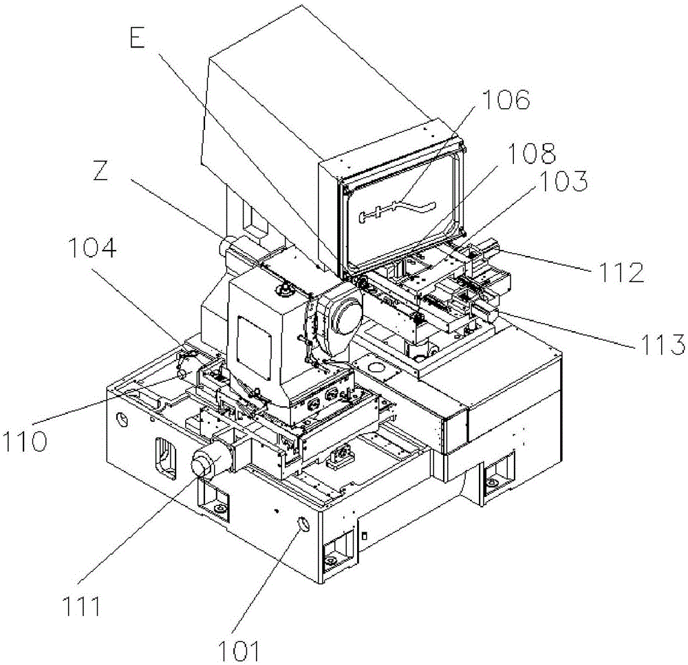
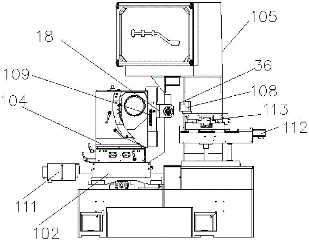
[0056] Such as figure 1 and figure 2 As shown, a CNC grinding machine with optical variable magnification includes a processing machine 101. The processing machine 101 is provided with an XY axis adjustment platform 102 and a UV workbench 103 for clamping workpieces. The XY axis adjustment platform 102 is provided with a Adjust the three-angle adjustment device 104 of the front, rear, left and right positions, the rear side of the processing machine 101 is provided with a rear support 105, and the rear support 105 is provided with an optical zoom projection device 106 with variable magnification, and the processing machine 101 is facing the optical zoom. A transmission light source 35 is provided below the magnification projection device 106, and a permanent magnet magnetic table workpiece mounting seat 108 is provided on the UV workbench 103, and the permanent magnet...


PUM


Abstract

The invention discloses an optic zooming CNC grinding machine, comprising a machining cabinet. The machining cabinet is provided with an XY axis regulation platform and an UV worktable for clamping a workpiece. The XY axis regulation platform is provided with a three-direction angle regulation device capable of regulating front and back and left and right positions. A rear bracket is arranged at the rear side of the machining cabinet. The rear bracket is provided with an optic zooming projection device with variable magnification times. A transmission light source is arranged at a position, exacting facing the optic zooming projection device, below the machining cabinet. The UV worktable is provided with a permanent magnetic table. The permanent magnetic table is positioned between the optic zooming projection device and the transmission light source, and the three-direction angle regulation device is provided with a cutting device. The optic zooming CNC grinding machine is high in grinding precision, convenient to adjust and has variable magnification times.

Description

technical field [0001] The invention relates to grinding equipment for processing workpieces, in particular to an optical zoom CNC grinding machine, a control system and a control method. Background technique [0002] At present, the existing CNC grinding machines have the following disadvantages: 1. The traditional optical grinding tool grinder controls the displacement and direction of movement of each cylinder by manually changing the flow and flow direction of each cylinder circuit by the operator, so that the oil in the two cylinders maintains a certain ratio Relationship, so that the grinding head on the grinding frame can obtain the corresponding curved track. Machining accuracy and efficiency are very low. 2. The optical tool grinding machine transformed by numerical control is not fully closed-loop controlled, the machining accuracy is unstable, and the error in machining cannot be compensated. 3. The optical tool grinder is horizontal. When clamping the workpiece...

Claims


Application Information

Patent Timeline
IPC IPC(8): B24B13/00B24B47/04G03B21/28
CPCB24B13/00B24B13/0031B24B47/04G03B21/28
Inventor 彭先奎
Owner DONGGUAN JOERG MACHINERY TECH
Why Eureka
Try Eureka